
")
- Details
Table of Contents
- Purpose
- General
- Responsibilities
- Guide Lines
- Flowchart (for the Netherlands only)
- References
- Attachments
1. Purpose
The purpose of this guide is to describe how the pump list, produced for submission to the Dutch Pressure Vessel Authority (currently named "Stoomwezen"), will be prepared and to provide information on its completion with relevant data.
2. General
The pump list is a document, which is based on the requirement set by the Dutch Pressure Vessel Authority to provide information on the type, the drive and the maximum differential pressure of pumps and compressors (ref. 6.1). It is a desirable document for grass roots process installations and a helpful document for existing installations.
The pump list has no formal status as a document and will, consequently, not be approved or stamped by the Dutch Pressure Vessel Authority. The submission of the information is a mandatory activity.
For non-Dutch projects, a pump list may be prepared if considered necessary or helpful for the assessment of design conditions (see also ref. 6.2 and 6.3); in such case, it is an internal Company document only and does not require submission to third parties.
3. Responsibilities
The Project Manager or his delegate has the overall responsibility for the preparation, checking and issue of the pump list.
The Project Engineering Group is responsible for the preparation of the pump list.
The Authority Engineering Group is responsible for the checking of the pump list and for providing advisory services during its preparation.
4. Guide Lines
4.1 Requirement for a Pump List
The Project Manager or his delegate should, in concert with the Authority Engineer, establish whether a pump list is necessary or desired for the project. He should also assign the individual engineer(s) responsible for the preparation of the pump list(s).
4.2 Form, Language and Document Numbering
4.2.1 Basic Form
The basic form is shown in Attachment 1 of this guide. The column numbers 1 through 11 in this Attachment have been added for easy reference and are not part of the form.
Blank pump list vellums are available with the Authority Engineering Group; see Attachment 2 for a copy. An 'electronic' version of the form can be developed per individual project if so desired.
4.2.2 Language
The language on the pump list should normally be Dutch for pump lists prepared for Dutch projects. The use of English is, however, generally accepted by the Dutch Pressure Vessel Authority.
4.2.3 Pump List Document Numbering
The pump list document lead number is defined in ref. 6.4 as '911' and should be used unless otherwise instructed by the Project Manager. A client document number should be added if required by the contract.
Note: For large projects, there may be more than one pump list; see Attachment 1.
4.3 Preparation
4.3.1 Supply of Data
The data for the columns 1 through 11 should be supplied by Process Engineering or taken from pump data requisition sheets and/or pump calculation sheets after these have been checked by Process Engineering.
The pump list can also be used for compressors and blowers.
4.3.2 Filling out the Pump List
The pump list should be filled out by the assigned project engineer(s) in cooperation with Process Engineering. Attachment 1 provides details for the various columns as necessary.
4.3.3 Completeness and Presentation of Data
The filled out pump list should be checked by the Authority Engineering Group for completeness and the way in which the data are presented. After this has been done, the list can be signed for 'checked'.
4.3.4 Approval and Issue
The pump list should be signed for approval and issue by the Project Manager or his delegate. After this step, the list is available for submission to the (Dutch) Pressure Vessel Authority. Client's comments are normally not collected, but the client is - also in the absence of contractual requirements regarding this point - entitled to receive a copy.
4.3.5 Actualization and Finalization of the Pump List
The pump list should be updated, at regular intervals, in accordance with information taken from (see also 4.4.2):
-
Measured performance curves of pumps and compressors, obtained from Procurement (Inspection or Vendor Document Handling Group).
-
Engineering flow scheme information on safety devices.
The Project Manager should decide whether "as built" finalization of the pump list is necessary.
4.3.6 Example of Completed Pump List
An example of a completed pump list is shown in Attachment 3.
4.4 Contacts with the Pressure Vessel Authority
4.4.1 Submission of the Pump List to the Pressure Vessel Authority
The pump list will be submitted to the Pressure Vessel Authority if desired or useful within the frame work of the assessment work done by that Authority. Such submission is, for Dutch projects, usually done by or via the Authority Engineering Group (see ref. 6.5).
4.4.2 Review by the Dutch Pressure Vessel Authority (Stoomwezen)
Stoomwezen will review during the assessment work the pump list and, during the preparation for the so-called "nader onderzoek" (see ref. 6.6), the test curve of each pump. Therefore, the pump list should reflect the actual situation and should be actualized from time to time (see ref. 4.3.5).
5. Flowchart (for the Netherlands only)
6. References
Document
Number Title Level
6.1 G-0401 Stoomwezen Rule "Behandelingsprocedures" -
6.2 BN-EG-UE1 Pressure Temperature Profile 5
6.3 BN-EG-UE2 General Rules to Establish Mechanical
Design Pressures and Temperatures 5
6.4 BN-W-UE301 Numbering of Project Documents 4
6.5 BN-EG-UE203 Submitting Information to Pressure Vessel
Authorities 5
6.6 BN-EG-UE206 "Nader Onderzoek" by Stoomwezen 5
7. Attachments
1. Notes regarding the preparation of the pump list (3 sheets).
2. Blank pump list form (1 sheet).
3. Example of completed pump list (1 sheet).
Notes Regarding the Preparation of the Pump List
1. Details For Filling Out The Various Columns
For the form and the numbering of the columns, see Attachment 2.
1.1 Columns 1, 3 and 11 (Pump Number, Density, Remarks)
The columns 1, 3 and 11 are self-explanatory. The molecular weight can be stated instead of the density for compressors and blowers.
1.2 Columns 2A and 2B (Capacity)
In the columns 2A and 2B the "normal" and "maximum" (rated) capacities as stated on the pump data requisition sheets should be indicated. The flows should be stated in kg/h for compressors and blowers.
1.3 Column 4 (Normal Suction Pressure)
Column 4 should state the suction pressure under normal operating conditions. Static head and tray pressure drop should be taken into account to avoid cumulative effects. For suction pressures below one (1) barg the use of the negative figure is preferred above the figure in bara.
Note: This is in accordance with Stoomwezen practices.
1.4 Column 5 (Maximum possible Suction Pressure)
Column 5 should indicate the suction pressure which occurs when the vessel from which is pumped is operating at the pressure for which it is protected or designed (i.e. opening pressure of relief valve or design pressure). Static head and tray pressure drop should be taken into account to avoid cumulative effects.
1.5 Column 6 (Normal Differential Pressure)
Column 6 should indicate the differential pressure at the (normal) operating point of the pump or compressor.
1.6 Column 7 (Maximum Differential Pressure)
Column 7 should indicate the maximum differential pressure. In the majority of cases, this will be at zero flow.
1.7 Columns 8 and 9 (Normal and Maximum Discharge Pressure)
Column 8 gives the sum of figures in columns 4 and 6, column 9 the sum of the figures in columns 5 and 7.
1.8 Column 10
Column 10 should indicate the setting of the discharge pressure safety device if installed. The setting shall normally be lower than the figure of column 9 and take static head effects into account.
Note: The preparation of the pump list may even lead to the conclusion, that such safety device is required.
The design pressure of the discharge piping - and sometimes equipment as well, depending upon how and where it is protected against overpressure - shall be equal to or higher than the figure of column 9, if no pressure safety device is or will be installed.
2. Shortcut Methods for First Issue
In some cases, the pump list will initially be prepared in an early stage of the project; pump and compressor curves, other that catalogue or proposal curves, are not available in that stage. For a reasonable estimate of the pressure levels, the following shortcuts can be used as a first approach:
2.1 For E-motor driven centrifugal pumps the maximum differential pressure should be taken as 120% of the normal differential pressure.
This figure should be checked against the actual figure once available (e.g. from the actually measured pump curve) and the necessary corrections should be made as necessary.
In some cases it is advisable to order pumps on basis of a specified maximum differential pressure; this does not replace the check against the measured pump curve!
Notes:
- Basically identical centrifugal pumps may still show different curves due to small differences between their impeller performance.
- Reciprocating pumps have almost always a pressure protection devise at their discharge side; the pump curve is, for these pumps, hardly a useful tool.
2.2 For turbine driven pumps the maximum differential pressure should be taken as 125% of the normal differential pressure; this figure should be checked against the actual figure once available (e.g. from the actually measured pump curve) and the necessary corrections should be made as necessary.
The design pressure of the equipment and piping in the discharge system should be carefully reviewed to establish the need for pressure protection devices.
3. Other Notes
3.1 Large projects usually involve more than one process unit; in these cases, it is advisable to prepare a pump list for each process unit. This will also simplify the communication with the Pressure Vessel Authority, if they require or use these pump lists.
3.2 Pumps with a dual service at different pressure levels should be treated with extra care. The discharge piping and equipment should be designed for the most severe possible combination of pressure and temperature up to and including the last block valve in the system. The pump list should, in such case, give the data for both services.
Note: Exceptions can sometimes be allowed for specific cases such as start-up lines and other infrequently occurring but carefully supervised operating situations. The decision to take such exception may be questioned by the Pressure Vessel Authority and should be well defendable.
3.3 Some chemical plants in particular can be sufficiently complicated to warrant a full investigation and qualification of all possible pumping circuits. Care should also be taken in situations, where two pumps may operate in parallel.
- Details
"Large parts of this procedure are not applicable anymore due to the recent European regulations such as PED"
Table of Contents
1. Purpose
The purpose of this guideline is to describe the way in which the "nader onderzoek" (final examination after installation) will be executed by Stoomwezen BV and which activities are required from the various Company Departments.
2. General
2.1 Terminology
The "Rules for Pressure Vessels" use the term 'pressure apparatuses' for equipment and systems under pressure, thus including vessels, reactors, heat exchangers, boilers, piping systems etc. The Rules are, in principle, made for Steam Act pressure apparatuses, but are also applied to Non-Steam Act pressure apparatuses (in the Netherlands generally known as "druktoestellen").
2.2 Justification of the "Nader Onderzoek" (Steam Act Pressure Vessels)
In accordance with the Steam Decree, section 12, subsection 5, (ref. 6.3) the examination of a steam or vapor apparatus also comprises a final examination, being an examination with regard to the set-up (or installation), lay-out and appurtenances of the apparatus.
The purpose of the examination is to satisfy Stoomwezen BV, that the plant or applicable part of it is safe and protected as intended by the Steam Decree. The detailed content of the examination is described in section 4 of this guideline.
2.3 Non-Steam Act Pressure Apparatuses
Non-Steam Act pressure apparatuses require only a "nader onderzoek" if the permit grant for the operating license of the subject facilities (based on the Environmental Management Act) contains a condition that such apparatuses have to be inspected by the "Dienst voor het Stoomwezen" or an organization accepted by the latter. For the purpose of this guide this accepted organization can be assumed to be Stoomwezen BV.
The formulation of this condition and its interpretation may vary from one permit grant to another.
2.4 Fulfillment of the Requirements of the Steam Decree
The Steam Decree (ref. 6.3) contains a large number of provisions regarding the appurtenances of steam and vapor vessels, which are elaborated, explained and supplemented in the "Rules for Pressure Vessels". With the exception of the provisions regarding:
-
safety valves, rupture disks and other appurtenances which serve to prevent that the allowable operating conditions will be exceeded, such as pressure, temperature and flow switches for cut out systems, and
-
appurtenances such as remotely operated level gauges on boilers,
these provisions are not verified by Stoomwezen BV on a preventive basis.
For documentation requirements see 4.2.4.
3. Responsibilities
The Authority Engineering Group, a member of which acts as Stoomwezen Coordinator (ref. 6.5 and 6.8), or the Representative/Deputy of the Stoomwezen Coordinator at site, has the prime responsibility for all coordination with Stoomwezen BV and guiding the activities to be performed by other Company Departments in relation to this guideline.
The Company Construction Department has the prime responsibility for the compilation of all field documents required and/or applicable for the "nader onderzoek" and for supporting the necessary activities in the field.
Other Company Departments involved in the "nader onderzoek" or aspects thereof may include, e.g., the Procurement Department (particularly the Inspection Group), the Engineering Department and the Process Department.
4. Guidelines
4.1 Timing, Request, Results and Duration
4.1.1 Timing of Execution
The "nader onderzoek" should be executed when the steam and vapor vessels have been erected (practically) "ready for operation", i.e. when the equipment items and the related other equipment inclusive of piping, control systems etc. are mechanically complete.
On larger projects, the "nader onderzoek" activities will normally be spread over a prolonged period, particularly for piping systems since these become ready over a longer period; combination with inspection work by a Stoomwezen inspector is recommended.
4.1.2 Request for "Nader Onderzoek"
The request for a "nader onderzoek" should be made in writing or by facsimile by the Stoomwezen Coordinator or by his representative/deputy at site. The request should be sent to the responsible Stoomwezen BV regional office for the attention of the agenda officer, at the latest about three (3) weeks in advance of the expected mechanical completion of the plant, unit or applicable part of it.
Before issuing the request it is advisable to check the following with the responsible Stoomwezen office :
-
how many equipment items are administratively ready for the ‘nader onderzoek’;
Note:
This information is usually available with the Coordinator as part of the document assessment activities.
-
which instrument testing is to be witnessed by Stoomwezen BV as part of the ‘nader onderzoek’ (for example : low level trips of boilers, temperature trips of furnaces, both simulated and actual)
-
Note:
-
In such cases, the instrumentation supervisor has to include such activities in his testing schedule in order to invite the Stoomwezen inspector.
Timing and extent of the "nader onderzoek" should be carefully coordinated with the Stoomwezen BV regional office because they need also some office time for preparatory activities. If done so, the examination will be effective and can take place as scheduled. See also 4.2.2.
4.1.3 Time Consumption of the "Nader Onderzoek"
Based on former experience, the "nader onderzoek" should be scheduled for approximately the following typical duration’s:
-
for a crude distillation unit 3 days
-
for a hydrotreater unit 1 day
-
for a distillate fractionation unit 2 days
-
for an amine unit 1½ days
-
for a utility distribution system 1½ days.
The duration for other types of units should be estimated in proportion with the above examples, noting that for practical reasons the duration should not be defined in periods shorter than ½ day.
If also a "nader onderzoek" for non-Steam Act pressure vessels ("drukvaten") is required, the duration can be estimated by multiplying the above figures with the ratio :
Steam vessels+vapor vessels+"drukvaten"steam vessels+vapor vessels
4.1.4 Result of the "Nader Onderzoek"
A successful completion of the "nader onderzoek" will result in the issue of a start-up permission to the client for the plant, the unit or part of it. Initially, such permission will have the format of a signed-off/stamped checklist or a simple written and signed/stamped document per item or system checked. The formal documents (CEOC-certificates, licenses and declarations of no objection) normally follow at a later date.
Pressure vessels and piping systems subject to licensing on basis of the Steam Act will receive a license. Pressure vessels subject to Stoomwezen inspection and acceptance on basis of the conditions of the environmental permit receive a declaration of no objection (“VGB”). All other pressure vessels inspected by Stoomwezen BV receive a declaration of manufacturing and first test (“VVB”).
4.2 Details of the Execution of the "Nader Onderzoek"
4.2.1 Systems Subject to a "Nader Onderzoek"
Systems subject to a "nader onderzoek" are all plants, parts of plants, plant systems and units, containing steam or vapor boilers and/or vessels, and/or piping systems subject to Stoomwezen approval.
For Non-Steam Act pressure vessels, which may include piping systems, the requirement for Stoomwezen approval exists only if the condition stated under 2.3 is fulfilled. The extent of the "nader onderzoek" then depends on the formulation of the condition of the permit grant.
No principle difference has been made between steam and vapor vessels and Non-Steam Act pressure vessels in 4.2.2 and further.
4.2.2 Appointment with Stoomwezen
The Company Construction Department, represented by the Coordinator's Representative/Deputy at site, should arrange for the appointment(s) with Stoomwezen BV to execute a "nader onderzoek".
For large(r) projects, the amount of work connected with the "nader onderzoek" -- including the office work which precedes the field activities -- is often sufficient to warrant formal scheduling by the Construction Department and prior discussion of the organization and the scheduling of the work with Stoomwezen BV (see 4.1.2).
4.2.3 Verification Activities by the Construction Department
Before the "nader onderzoek" can be started, the Coordinator's Representative/Deputy at site should verify or arrange for verification of the items listed below.
Nameplates and identification marks
Verify that the Stoomwezen nameplates and/or identification marks on all steam and vapor boilers and steam and vapor vessels are in accordance with the Stoomwezen rule on identification marks (ref. 6.6) and with the latest issue of the classification list(s) (ref. 6.2). If the "nader onderzoek" comprises also Non-Steam Act pressure vessels, then the same is applicable for all Stoomwezen nameplates on these vessels. Differences such as errors, missing data etc. should be reported to the Stoomwezen Coordinator to enable finalization of the classification list(s).
Verify that these Stoomwezen nameplates have been stamped on all four rivets or on all tack welds between equipment and nameplate with either the Stoomwezen symbol (lion) or with the corresponding symbol of the non-Dutch third party organization.
Notes:
-
Piping systems and very small vessels (volume equal to or less than 0.01 m3 normally do not have a nameplate; for these cases, the Stoomwezen symbol is stamped near the registration number, usually in front of or at the end of this number, or both.
-
Equipment that has been fabricated outside the Netherlands and that has been inspected by a local Third Party organization under the terms of EEC guideline 76/767/EEG (ref. 6.7), should have been stamped with the symbol of this Third Party Organization, who should be a member of the CEOC organization (see Attachment 3 of ref. 6.4).
Piping materials and systems
Verify that all piping materials and piping systems have been treated as described in the Guide for Coordination with Stoomwezen BV (ref. 6.8).
This implies in particular verifying that :
- marking and remarking of 'Stoomwezen' piping and fittings (with, e.g., heat number, factory mark, third party inspector stamp) have been carried out properly by the piping material manufacturers and the piping construction subcontractor;
- material certificates required by the "Rules for Pressure Vessels" and/or the Stoomwezen BV approval letters ("Nieuwbouwrapporten") for piping systems are available for the Stoomwezen BV inspector;
- all welding has been executed in accordance with the "Rules for Pressure Vessels" and/or the Stoomwezen BV approval letters for piping systems (properly qualified welders, welding procedures accepted by Stoomwezen BV, or, if fabricated outside the Netherlands, by an accepted local Third Party Organization etc.);
- test results such as radiographic films (with location plans), ultrasonic, magnetic particle and dye penetrant reports and hydrostatic test reports are available for the Stoomwezen BV inspector;
- reports on special treatments such as heat treatment are available for the Stoomwezen BV inspector;
- Stoomwezen BV register and -- if issued -- sequence numbers and the stamp of the Stoomwezen BV inspector who inspected the pipe spools before installation have been properly marked on the piping systems.
Notes:
-
Sometimes the register number will be placed on a weld-on plate.
-
Some piping shops have received a delegacy from Stoomwezen BV for pipe spool marking; in such cases, the stamp shall be placed by the assigned person of the piping shop.
-
For piping spools or systems fabricated outside the Netherlands, an inspector of a local Third Party Organization -- being member of the CEOC organization -- will often provide the stamping.
all information on the tag plates of safety valves matches with the safety valve certificates, referencing the safety valve item numbers on the classification list.
blow off lines of safety valves have open ends and that no obstructions (valves etc.) are located in these ends.
all relevant forms are legible, complete, signed and stamped by the manufacturer and/or piping construction subcontractor;
the latest issues of engineering documents such as engineering and utility flow diagrams, line designation tables and, for piping systems subject to formal stress assessment, the overall piping system drawing(s) is (are) available (see 4.2.4, B).
Notes:
-
It is recommended to prepare a centralized file of all documentation for this "nader onderzoek" and to ensure that the various documents can be easily related to each other by, e.g., using the heat numbers; this promotes the information retrieval and saves time during this last phase of the construction work. When agreed so with the Stoomwezen BV Inspector, he should be provided with storage facilities which are only accessible to himself.
-
To facilitate the checking of certificates by the Stoomwezen Inspector, a compilation should be made for each category of certificates, containing information such as size of the piping components involved, the heat number and the charge number. A number of columns should be included for use by the Inspector.
-
By acting in this way, the field inspection by Stoomwezen BV can, for piping systems, be limited to field welds, hydrostatic testing (if not yet done), register number checking, pipe supports checking on type, location and sometimes, operability and late changes to (parts of) the piping systems, if any.
-
For large(r) projects, a considerable portion of the 'paper work' should be (and is) done beforehand by Stoomwezen BV in order to reduce the field effort for the "nader onderzoek", i.e. during the piping (pre)fabrication and erection activities. The centralized file addressed under note 1 above will be a good tool for this work.
It is recommended that the verification activities will be performed, to the extent reasonably possible, at the receipt of equipment and materials, or otherwise during the installation activities.
4.2.4 Compilation of Documents
Before the "nader onderzoek" starts, the following documents should be compiled:
A. by the Authority Engineering Group (for submittal to Stoomwezen BV):
-
(copies or originals of) Test and Measuring Certificates ("meetbrieven") of safety valves and rupture discs in the plant, part of plant or system;
-
(copies of) test curves of pumps, compressors and blowers;
-
Note:To be submitted by manufacturer through the Company Inspection department.
-
further information and data as requested by Stoomwezen BV during the main procedure, for example information on alarm settings live tests, details on locking systems etc.
The desired documents and information should have been specified by Stoomwezen BV during the main procedure. The main procedure documents such as classification lists, line designation tables and engineering flow diagrams will have been submitted to Stoomwezen BV up to and including their latest issues as part of the main procedure (ref. 6.10).
Additionally, the following documents shall be submitted:
- the original CEOC-certificates as prepared by the local Third Party Organizations for equipment fabricated outside the Netherlands
- the manufacturing data books as prepared by the foreign manufacturers for equipment fabricated outside the Netherlands.
Notes:
-
These documents should, according to the Rules, be submitted by the manufacturers or the local Third Party organizations involved; since this does not always happen, follow up by the Inspection and/or the Authority Engineering group is necessary.
-
A verification by Company of both sets of documents to ensure that both show the same and the correct data is recommended to avoid delays and extra work due to non-acceptance by Stoomwezen BV.
B. by the Company Construction Department (to be available for the Stoomwezen Field Inspector:
-
(copies of) the Test and Measuring Certificates( “Meetbrieven”) of the relevant safety valves and rupture discs in the plant, part of plant or system;
-
(copies of) test curves of pumps, compressors and blowers;
-
all relevant engineering and utility flow diagrams;
-
copies of the classification list, the line designation tables (see 4.2.3, under “Piping Materials and Systems”) and any other documents as indicated by the Stoomwezen Coordinator.
4.2.5 Assistance to Stoomwezen BV
During the "nader onderzoek", the Coordinator's Representative/Deputy at site should be available or arrange for the availability of an engineer to assist Stoomwezen BV and/or to be present with the examinations.
4.2.6 Stoomwezen BV Activities
During the "nader onderzoek", Stoomwezen BV will execute the following activities.
A. Office activities:
-
check of all engineering and utility flow diagrams for the safety protection of equipment;
-
check of all test curves of pumps, compressors and blowers as specified by themselves;
-
check of test and measuring certificates of safety valves and rupture discs, as specified by themselves;
Note:
Safety valve certificates comply with Stoomwezen requirements if they contain information on (1) the height of the government ring (2) the spring diameter, the spring wire thickness, the unloaded spring length and the number of windings.
-
verification of the further information and data as requested by themselves during the main procedure (see 4.2.4);
-
verification of the original CEOC-certificates received from the Authority Engineering Group, from the manufacturers or from the local Third Party Organizations for equipment fabricated outside the Netherlands, against the manufacturing data books and the classification lists; these documents will be kept by Stoomwezen BV for the preparation of licenses and declarations of no objection
-
verification of the manufacturing data books received from the Authority Engineering Group, from the manufacturers or from the local Third Party Organizations, for compliance with the inspection requirements contained in the approval letters of the equipment fabricated outside the Netherlands; these documents will be returned by Stoomwezen BV after review and acceptance.
This document checking will, whenever possible, be done in the Stoomwezen BV office in order to minimize their field activities, particularly on smaller projects where no Stoomwezen BV inspector will be permanently assigned to the project.
The results of the checking and verification activities is laid down in a so-called 'Nader onderzoek rapport' for the individual equipment items and piping systems subject to a license, a declaration of no-objection or inspected and tested on specific Company/Client request.
Note:
Equipment items and systems NOT subject to a license or a declaration of non-objection are normally not checked by Stoomwezen BV.
B. Activities for equipment constructed at site:
For equipment items that are constructed or erected at site, either entirely or from pre-assembled parts, some Stoomwezen related activities are required at site; typical examples include large storage vessels including spheres and large furnaces, boilers and heaters.
Such activities include (without necessarily being complete):
-
contacts with Stoomwezen BV for fabrication inspection, final inspection and acceptance at site
-
definition of hold points with and for Stoomwezen BV inspection (e.g., fit ups)
-
document review by Stoomwezen BV
-
definition of hold points with and for Stoomwezen BV inspection (e.g., fit ups)
-
document review by Stoomwezen BV
-
hydrotest in the presence of Stoomwezen BV
-
the "nader onderzoek" by Stoomwezen BV when all piping has been connected and all appurtenances have been installed
-
stamping of nameplate by Stoomwezen BV at successful completion of the "nader onderzoek".
These activities are normally included with the subcontract for construction/erection.
The Coordinator's Representative/Deputy has only a supervisory role for these activities.
C. Field activities:
-
visual field check of the plant or units as installed against the engineering and utility flow diagrams;
-
field check of all steam and vapor boilers and vessels for registration number and Stoomwezen BV or CEOC member symbol on the nameplates; in case also "drukvaten" have to be inspected the same applies to these vessels;
-
presence with hydrotests of piping systems if done at site;
-
field check of safety valves, including interlock systems etc., as installed;
-
presence during the blow-off of boiler safety valves;
-
check on the proper functioning of automatic starting devices for spare pumps, the cut-out systems for, e.g., furnaces and reboilers and/or other essential safety systems;
-
any further check on safety systems as required by themselves; such further checks will normally have been specified during the main procedure for the project (see ref. 6.9/6.10).
4.2.7 Follow-up on Stoomwezen BV Activities
Any notes or remarks made and/or any corrective actions specified by Stoomwezen BV during the "nader onderzoek" should be resolved or executed on a mutually agreed basis. This includes corrections of administrative nature such as removal of errors in CEOC-documents.
Stoomwezen BV may, at their option, issue a conditional start-up permission or hold this permission until the outstanding points have been cleared.
Note:
The so-called 'hold points' are often related to essential safety items; the emphasis is laid on equipment items and systems subject to a license or a declaration of non-objection, since non-compliance’s with these items or systems may have juridical consequences for Stoomwezen BV.
5. Preparation of the Guide for Projects
Because each project is different again the above guidelines should be reviewed when they will be used for a project. For smaller projects some simplifications may be possible, for other projects additional agreements with Stoomwezen BV may be useful.
If it is decided to modify the guidelines for a specific project, a separate document should be issued for this project.
In turn, specific experiences from a project may lead to an update or modification of these guidelines.
6. References
|
Document Number
|
Title
|
Level
|
|
| 6.1 | BN-EG-UE203 | Defining Information to be Submitted to Pressure Vessel Authorities | 5 |
| 6.2 | BN-EG-UE214 | Preparation of Equipment Classification Lists for the Dutch Pressure Vessel Authorities | 5 |
| 6.3 | G-0203 | Steam Decree (1953, with updates) as contained in the "Rules for Pressure Vessels" | - |
| 6.4 | G-0301 | Stoomwezen Rule, "General Procedure" | - |
| 6.5 | G-0401 | Stoomwezen Rule, "Procedures for Pressure Vessels in Installations" | - |
| 6.6 | G-0601 | Stoomwezen Rule, "Identification Marks" | - |
| 6.7 | 76/767/EEC | Guideline Regarding the Acceptance of Inspections Executed by Local Inspection Organizations | - |
| 6.8 | BN-EG-UE... (later) | Guide for Coordination with Stoomwezen BV | 5 |
| 6.9 | BN-EG-UE217 (later) | Guide Regarding Procedural Information Stoomwezen BV | 5 |
| 6.10 | BN-EG-UE218 (later) | Guide for Information to be Submitted to Stoomwezen BV | 5 |
Note:
References 6.9/6.10 are available as Attachments 1 and 2 of Ref. 6.1, Defining Information to be Submitted to Pressure Vessel Authorities (BN-EG-UE203).
- Details
This is a LIVE STUDY document and will be changed without notice. The content may contain errors and omissions.
|
ASME B31.1 (2008) |
ASME B31.3 (2008) |
ASME B31.8 (2007) |
|---|---|---|
|
Power piping: typically found in electric power generating stations, in heating and cooling systems |
Process piping: typically found in petroleum refineries, chemical, pharmaceutical, textile and paper plants |
Gas transportation and distribution systems: piping transporting products, predominantly gas |
|
Applicable: boiler external piping from first joint up to and including first block valve for boilers where:
Excluding: fatigue due to pressure cycling
|
Exclusions:
Including: fatigue due pressure cycling and thermal cycling
|
Exclusions:
|
|
Allowable stress:
|
Allowable stress:
|
Allowable stress:
|
|
Materials: material of unknown specification shall not be used for pressure containing components |
Materials: material of unknown specification shall not be used for pressure containing components |
Materials: material only as per Appendix A |
|
Quality factor E: depending type of weld, radiography and material |
Quality factor E: depending type of weld, radiography and material |
Quality factor E: depending type of weld, radiography and material |
|
Factor y: factor depending Ferritic, Austenitic, Nickel and design temperature |
||
|
Factor W: weld strength reduction factor |
Factor W: weld strength reduction factor |
|
|
Factor f: stress range factor |
||
|
Factor F: design factor |
||
|
Factor T: temperature derating factor, compensate material allowable stress values for temperature, Table 841.166A |
||
|
Pipe under internal pressure (104.1.2 and 104.1.4 (in creep)):
P = internal design pressure D0 = outside diameter of pipe SE = maximum allowable stress, including quality factor tm = minimum required thickness y = coefficient table 104.1.2A A = additional thickness to compensate threading, provide additional strength, corrosion allowance W = Weld strength reduction factor when in creep range, is 1 outside creep range (table 102.4.7) |
Pipe under internal pressure (304.1.2):
P = internal design pressure D = outside diameter of pipe S = stress value for material E = quality factor t = pressure design thickness y = coefficient, also from table 304.1.1 W = Weld strength reduction factor |
Pipe under internal pressure (841.11):
P = internal design pressure D = nominal outside diameter of pipe S = specified minimum yield strength E = longitudinal joint factor, table 841.115A t = wall thickness F = design factor from table 841.114A T = Temperature derating factor from table 841.116A |
|
Bend under internal pressure (102.4.5):
pipe under internal pressure where I for intrados is:
and I for the extrados is:
and at sidewall I = 1.0, R = radius of pipe bend
|
Bend under internal pressure (304.2.1):
pipe under internal pressure where I for intrados is:
and I for the extrados is:
and at sidewall I = 1.0, R = radius of pipe bend
|
Bend under internal pressure (841.231): For cold bends the deflection of longitudinal axis and the radius is limited according table in paragraph 841.231
Hot bends are to be designed and manufactured according ASME B16.49, the internal pressure rating shall not be less than that which is calculated for straight seamless pipe and the intrados wall thickness should be:
where the t the wall thickness of the pipe is
|
|
Elbows under internal pressure (102.4.5): Elbows manufactured according standards listed in Table 126.1 are suitable for use at the pressure-temperature ratings specified by such standards.
Elbows not according above standards or for which design formulas and not given in the code shall be based on calculations consistent with the design criteria of this code. These calculations shall be substantiated by one or more of the means stated in A B C or D of 104.7.2 (Does this mean or allow that an elbow can be calculated according a bend with uniform thickness? Refer B31.3) |
Elbows under internal pressure (304.2.1): Elbows manufactured according standards listed in Table 326.1 are suitable for use at the pressure-temperature ratings specified by such standards.
Elbows not according above standards or for which design formulas and not given in the code shall be based on calculations consistent with the design criteria of this code. These calculations shall be substantiated by one or more of the means stated in A B C or D of 304.7.2, or the elbow can be calculated according the Bend calculation, refer 304.2.2. |
Elbows under internal pressure (841.231?): No specific design rules are listed for fabricated elbows
(Does this mean or allow that an elbow can be calculated according a bend with uniform thickness? Refer B31.3) |
|
Miter bends under internal pressure (104.3.3): 1. Only straight pipe calculations required if:
2. Pressure shall be limited to 70 kPa if:
and thickness is not less than required for straight pipe 3. Pressure shall be limited to 700 kPa if:
and thickness is not less than required for straight pipe 4. For pressure over 700 kPa: proof test, FEA, etc required with a defined minimum for closely spaced and widely spaced miter bend
|
Miter bends under internal pressure (304.2.3): 1. When theta =< 22.5 deg than max. allowable pressure shall be the lesser of (t = T - c):
and
2. When theta > 22.5 deg than max. allowable pressure shall calculated as (t = T - c):
For all miter bends the R1 shall not be less than:
with A: (T-c) =< 13 mm → A = 25 13 < (T-c) =< 22 mm → A = 2(T-c) (T-c) > 22 mm → A = 2(T-c)/3 + 30 |
Miter bends under internal pressure (841.232): 1. If system hoop stress > 40% of specified minimum yield strength miter bends are not permitted. Deflections caused by misalignment up to 3 deg are not considered as miters. 2. If 10% < hoop stress < 40% SMYS the deflection of each miter shall not exceed 12.5 deg. 3. If hoop stress < 10% SMYS the total deflection angle shall not exceed 90 deg. 4. If hoop stress > 10% SMYS the distance measured at the crotch shall not be less than one pipe diameter
|
|
Reducer under internal pressure (104.6): 1. Flanged reducer according Table 126.1 are considered suitable at the specified pressure temperature ratings. 2. Where butt welding reducers are made to a nominal pipe thickness, the reducers shall be considered suitable for use with pipe of the same nominal thickness. 3. Components not covered by the standards listed in Table 126.1 shall be based on calculation consistent with this code. Calculations are to be substantiated by one of: - extensive, successful service experience - experimental analysis - proof test - detailed stress analysis, such as finite element analysis (Is ASME VIII div.1 UG32 acceptable?) |
Reducer under internal pressure (304.6.1(b)): 1. Reducers according Table 326.1 shall be considered suitable for use at established pressure-temperature ratings or corresponding straight pipe with 87.5% of nominal wall thickness. 2. Concentric reducers not listed in Table 326.1 may be designed according closures as per ASME VIII div.1 3. Eccentric reducers not listed in Table 326.1 are qualified as unlisted components and shall be designed and documented substantiated by one of: - extensive, successful service experience - experimental analysis - proof test - detailed stress analysis, such as finite element analysis (Is ASME VIII div.1 UG32 acceptable?) |
Reducer under internal pressure (831.373): 1. Steel butt welded fittings shall comply with ASME B16.9 or MSS Standard Practice and shall have pressure and temperature ratings based on stresses for pipe of the same of equivalent material (831.31b) 2. Other pressure containing components shall be designed the according design philosophy of this code substantiated by one of: - extensive, successful service experience - experimental analysis - proof test - engineering calculations 3. Closure heads such as flat, ellipsoidal, spherical or conical heads are allowed for use under this code. Such items may be designed in accordance with ASME VIII div.1 (UG32). |
|
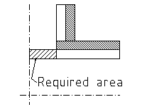
Stubon under internal pressure (104.3.1(D)): Required reinforcement area is
with
tr is reinforcement pad thickness
Assessment: Area A2,A3, A4 and A5 to be multiplied by the ratio of allowable working stress, maximum multiplication factor is 1.0 (para. 104.3.1(D.2.3))
|
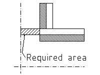
Stubon under internal pressure (304.3.3): Required reinforcement area is
Assessment: Area A2, A3 and A4 to be multiplied by the ratio of allowable working stress, maximum multiplication factor is 1.0 (para. 304.3.3(f3))
If |
Stubon under internal pressure (831.4 and app. F): Required reinforcement area is (Fig. F-5):
Assessment: Area A2 and A3 to be multiplied by the ratio of allowable working stress, maximum multiplication factor is 1.0 (para. 831.4(f))
|
|
Tee (extruded outlet) under internal pressure (104.3.1(G)): Required reinforcement area is
K = 1.0 when K = K = 0.7 when
Assessment: |
Tee (extruded outlet) under internal pressure (304.3.4): Required reinforcement area is
K = 1.0 when K = K = 0.7 when
Assessment: If If |
Tee (extruded outlet) under internal pressure (831.4 ref. App. F): Required reinforcement area is
K = 1.0 when d/D > 0.60 K = 0.6+(2d)/(3D) when 0.15 < d/D <= 0.60 K = 0.7 when d/D <= 0.15
Assessment:
|
|
Weldolet (branch) under internal pressure (104.3.1(D)): Required reinforcement area is
with
Assessment: Area A2,A3, A4 and A5 to be multiplied by the ratio of allowable working stress, maximum multiplication factor is 1.0 (para. 104.3.1(D.2.3)) |
Weldolet (branch) under internal pressure (304.3.3): Required reinforcement area is
with
Assessment: Area A2, A3 and A4 to be multiplied by the ratio of allowable working stress, maximum multiplication factor is 1.0 (para. 304.3.3(f3)) |
Weldolet (branch) under internal pressure (831.4 ref. App. F): Required reinforcement area is (Fig. F-5):
Assessment: Area A2 and A3 to be multiplied by the ratio of allowable working stress, maximum multiplication factor is 1.0 (para. 831.4(f)) |
|
Cap under internal pressure (104.4.1(B)):
Can be calculated with ASME VIII div.1 UG-32 app.1-4
L = radius dish r = radius knuckle
|
Cap under internal pressure (304.4.1(b)): Can be calculated with ASME VIII div.1 UG-32 app.1-4
L = radius dish r = radius knuckle
|
Cap under internal pressure (831.372 and 831.373): Can be calculated with ASME VIII div.1 UG-32 app.1-4
L = radius dish r = radius knuckle
|
|
Flat closure under internal pressure (104.4.1(b)): Can be calculated with ASME VIII div.1 UG 34 …
|
Flat closure under internal pressure (304.4.1(b)): Can be calculated with ASME VIII div.1 UG 34 …
|
Flat closure under internal pressure (831.373): Can be calculated with ASME VIII div.1 UG 34 … |
|
Flange under internal pressure (104.5.1(B)): Can be calculated according ASME VIII div.1 app. 2 using B31.3 allowable stresses and temperature limits with:
|
Flange under internal pressure (304.5.1(b)): Can be calculated according ASME VIII div.1 app. 2 using B31.3 allowable stresses and temperature limits with:
|
Flange under internal pressure (831.2): Allowed to use: ASME B16 series as listed in Appendix A such as B16.5. Also MSS SP-44. For slip-on welding flanges reference is made to ASME VIII div.1 design.
Can ASME VIII div.1 be used for calculation? |
|
Blind flange under internal pressure (104.5.2(B)): Can be calculated according ASME VIII div.1 UG-34 with:
|
Blind flange under internal pressure (304.5.2(b)): Can be calculated according ASME VIII div.1 UG-34 with:
|
Blind flange under internal pressure:
Can ASME VIII div.1 be used? |
|
Blanks (spade) under internal pressure (304.5.3(B)):
|
Blanks (spade) under internal pressure (304.5.3(b)):
|
Blanks (spade) under internal pressure:
Can ASME VIII div.1 be used? |


- Details
Company
Engineering procedure for the preparation of process flow diagrams P-T profiles engineering flow diagrams utility flow diagrams interconnecting flow diagrams process safeguarding flow diagrams revamping flow diagrams and line tables
Table of content
-
Introduction
1.1 Purpose
1.2 Concept
1.3 Use
1.4 Types of Diagrams
1.5 Notes -
Scope
-
General procedure for flow diagram preparation
3.1 Layout and Format
3.2 Symbols and Identification
3.3 Diagram Issues -
The process flow diagram
4.1 General
4.2 Initial Process flow diagram
4.3 Kickoff Meeting
4.4 Process flow diagram drafting
4.5 Reissues of process flow diagrams
4.6 Computer vision diagram systems -
The Pressure (p) – Temperature (T) profile
5.1 General5.2 Purpose
5.3 Reissues of P-T Profile
5.4 Computer Vision Diagram Systems -
The Engineering flow diagrams
6.1 General
6.2 Initial Engineering flow diagram
6.3 Pipelines and pipelines referencing
6.4 Initial flow diagram check
6.5 Diagram review meeting
6.6 Engineering flow diagram drafting6.7 Reissues of Engineering flow diagrams
6.8 Computer vision diagram systems -
The utility flow diagrams
7.1 Purpose
7.2 Preparation
7.3 Layout
7.4 Control systems, valves, etc.7.5 Equipment
7.6 Example diagram
7.7 Example diagram -
The interconnecting flow diagrams
8.1 Purpose8.2 Split of work
8.3 Layout
8.4 Example diagram -
The process safeguarding flow diagrams
9.1 Introduction
9.2 General consideration
9.3 Purpose
9.4 Timing and preparation of process safeguarding flow diagram
9.5 Presentation -
The revamping flow diagram
10.1 General
10.2 Updating and Marking engineering flow diagrams10.3 Example diagram
-
Check list
-
preparation of line tables
12.1 Responsibility
12.2 Format
12.3 Description of Columns
12.4 Procedure
12.5 Computer vision systems
12.6 Sample forms -
List of related Company standards
-
List of standards other than Company
14.1 General
14.2 U.S.A.
14.3 West Germany
14.4 Great Britain
14.5 France
14.6 The Netherlands
14.7 S.I.P.M.14.8 Aramco
-
Typical arrangements of equipment installation
15.1 General
15.2 Vessels and columns
15.3 Shell & Tube heat exchangers
15.4 Aircoolers
15.5 Pumps
15.6 Turbines
15.7 Ejectors
15.8 API
15.9 Control stations15.10 Utility tie-ins into process lines
15.11 Battery limits installations
15.12 Sample stations
15.13 Safety relief valves
15.14 Burner installations15.15 Steam trap assemblies
15.16 Instrument purges
15.17 External seal flush and purge
15.18 Cooling rotating equipment15.19 Flushing oil
15.20 Blowdown systems
15.21 Level instruments and stand pipes
15.22 Instrumentation compressors
15.23 Valve type selection
15.24 General instrument requirements15.25 Utility header valve requirements
1. Introduction
1.1 Purpose
The purpose of this document is to outline the procedures for the preparation of process flow diagrams, pressure-temperature profile diagrams, engineering, utility and interconnecting flow diagrams and special diagrams as revamp flow diagrams and pressure safeguarding flow diagrams.
1.2 Concept
Flow diagrams are highly specialized “language” for information transfer. They represent the engineer's concept of how plant equipment should be interconnected. The diagram is almost physical in a sense, since every piece of equipment, every pipeline, valve and instrument is shown. Diagrams are used to convey information between groups working on the project and translate the plant design into “real” piping and equipment.
1.3 Use
By preparing the diagrams properly, the engineer can convey a great deal of technical information, quickly and accurately, with a limited amount of paper work.
1.4 Types of diagrams
There are 7 types of flow diagrams:
1.4.1 The process flow diagram (PFD)
The PFD is developed by the process engineering department. Final drafting by the flow diagram squad.
On this document are given the main process equipment., fluid flows, main control loops and critical valves. It is a tool for the process engineer(s) to convey information to project and specialist engineers to design the installation in detail (see fig: 6)
1.4.2 The Pressure Temperature Profile Diagram (PTP)
The PTP diagram is a document prepared by the Process Engineering Department with the purpose of providing project, control systems and piping engineers with the correct pressure and temperature correlations between the various piping systems, vessels, exchangers, etc.
The document ensures that proper values are being used for preparation of data sheets, line tables and other documents as, e.g. painting systems, insulation, etc.
For PTP preparation procedures refer to Standard Specification BN-EG-UE-1 (Design guide for Pressure and Temperature profile).
1.4.3 The Engineering Flow Diagram (EFD)
On this document are shown all equipment connecting piping, utility piping, complete with control loops and all other instrumentation, all valves and safety measures. It is the main tool for the project engineer to convey information to the piping design office and control systems engineering group for the detailed piping and control systems design (see fig:13)
1.4.4 The Utilities Flow Diagram (UFD)
This document shows how utilities are generated and distributed from the source or supply point to the various parts of an installation. The diagram shows common control loops, additional equipment that is deemed necessary to supply the utility as required and the safety measures necessary (see fig: 18). The diagram shall be drawn in accordance with the geographical layout of the plant.
The diagrams are generally divided per generation activity, e.g. steam generation, instrument air, cooling water, fuel oil, etc. The utility equipment shall be shown. Packaged units to be shown within heavy dotted line.
1.4.5 The Interconnecting Flow Diagram (IFD)
These diagram are prepared to show the interconnecting lines between various plant units and, e.g. tank farms, etc.
1.4.6 The Process Safeguarding Flow Diagram (PSFD)
This document shows the correlation of safety devices installed but indicated on separate EFD's. It “highlights” the final level of protection provided by the safety systems installed.
This document will be produced on client's request only, e.g. SIPM.
1.4.7 Revamp Flow Diagram (RFD)
“Revamping Flow Diagram” shall be prepared to indicate which equipment, lines, control loops, etc. must be demolished, modified, removed or relocated, etc. in a revamping project. The existing engineering flow diagrams of a plant or unit to be revamped shall be used.
In general two sets of diagrams are to be prepared:
a. An updated existing EFD's version for demolishing purposes RFD's.
b. New “as built” EFD's
For more details refer to chapter 10
1.5 Notes:
1.5.1 It must be noted that particular instructions given by client or licensor with respect to his requirements or special requirements covered by any authority decrees shall be observed.
1.5.2 If any of such rules, decrees or instructions exist, these must be mentioned in the “Project Specification”.
1.5.3 When these instructions have not been incorporated, the documents produced will be unacceptable to the client or licensor and/or authorities.
1.5.4 Where in the following text of this Engineering Procedures has been referred to other Company procedures or standards, this is only true where the Company standards are not conflicting with those mentioned under par 1.5.1.
1.5.5 To obtain maximum uniformity with regard to line thickness, lettering, symbols, etc. the drafting on vellums shall be executed by the Flow Diagram Squad.
1.5.6 There is still another flow diagram, prepared by the control systems engineering group, exclusively for use by process and control systems engineers. This flow diagram is principally a PFD on which the control system engineer indicates specific instrument physical data: the document is called: “Instrument Data Flow Sheet”. It is not further mentioned in this “Engineering Procedures”.
1.5.7 The examples presented in this Engineering Procedure are taken from actual jobs and include general Client's requirement. Therefore, the symbols used will not always be identical to the symbols shown on the legend sheet fig:22
1.5.8 On an EFD, a package unit, e.g. compressor, can be indicated with a heavy drawn block with reference to one or more vendor flow diagram (process, lube oil, seal oil, water cooling, etc.) which can be adopted.
2. Scope
2.1 This Engineering Procedure shall be used as a standard for the preparation of precess and engineering flow diagrams as outlined in para 1.4 of the introduction.
2.2 It shall also be used to edit systematically the text for the project specification on the subject of flow diagram preparation.
2.3 The purpose of this Engineering Procedure is to provide the engineers with all necessary information to generate the various diagrams needed with the greatest consistency and efficiency possible.
3. General Procedure for flow Diagram Preparation
3.1 Layout and Format
3.1.1 Vellums
All formal diagrams shall be drawn on standard A-1 size vellums (vellum size 594x841mm, including 10mm edge). In those cases where the project specifications ask for drafting on client's standard forms, the size may be different from the A-1 size.
3.1.2 Title block
The PFD, EFD and other diagrams shall bear in the right hand bottom corner of the diagram the standard Company title block. In cases where project specifications ask for specific use of client's vellums with client's title block, a standard Company drawing number sticker shall be added to the drawing for use of Company drawing record (see figure 1a).

Fig. 1a
In cases where client forbids the use of Company drawing number sticker, the Company drawing number shall be outside the drawing boundary line (see fig:1b).
The title block shall be completed with information as unit number unit name, unit section, drawing number, and all other information that is necessary to give all drawing-related information.
3.2 Symbols and Identification
3.2.1 For each project the engineering and utility flow diagrams will use the Company standards, if not overruled by client's licensor's or authority's requirements. These technical documents are:
BN-DS-C1 General information and Explanation of the Company symbols
BN-ES-C1 Standard symbols for Process and Engineering Flow Diagrams
BN-ES-K1 Standard for Identification of Instruments.
3.2.2 All symbols, instrument identifications and abbreviations used must be conform to those shown in above given standards, unless otherwise noted in the project specification.
In other cases a new legend sheet is to be prepared, which includes the required symbols and abbreviations. Project shall decide, in consultation with client or licensor, which system has to be used.
3.2.3 All equipment shown on the process and engineering flow diagram shall be identified with both name and number as listed on the equipment list.
Placement of titles shall be as follows:
a) Towers, tanks, tubulars, general equipment and other items on or above the upper base line shall be identified with titles placed across the top of the diagram. In some cases a space shall be provided to indicate design and/or operating conditions.
b) Pumps, compressors, etc. on the lower base line. Space shall also be provided to give design/operating conditions, if required.
3.2.4 To save drafting time, the flow diagram squad may make use of preprinted self-adhesive stickers to be stuck to the front or the back of the flow diagrams. These stickers can be adapted to any project an requirement.
3.2.5 Sticker samples
3.3 Diagram Issues
3.3.1 Issue numbering
It is of utmost importance that flow diagrams are kept up to date continuously and are regularly to keep all disciplines informed of the change during the engineering stage.
A release for design issue of flow diagrams shall be made directly after incorporation of Client's comments. Any further change after this issue mad by the Client shall be a subject for a change order.
The reissues shall be distributed in accordance with the job document distribution schedule.
All issues shall be numbered, dated and provided with a short description of the reason for reissue in accordance with QA procedure 006.
Typical example
The issue number shall be in accordance with the required numbering system as given in the job project procedure.
3.3.2 Revision list
All issues distributed after the “preliminary piping materials B.T.O.” shall be accompanied by a “revision list” on standard form BN-UD-101 “List of Revisions”.
This list of revisions (change) shall be issued as an addendum to the revised flow dagram. Each new diagram issue shall be accompanied by such a list of revisions.
3.3.3 Internal Issues
In some cases it may be required to distribute a diagram exclusively for the use within the BBV organization only.
It shall be clear that the number of such “Internal Issues” shall be kept to an absolute minimum. It is even better to have none at all.
In the case however, that an internal issue is necessary, the numbering procedure is as follows:
A circle of 16 mm diameter shall be drawn at the left hand side of the diagram title block and on the backside of the vellum. The circle shall be divided in two parts by a horizontal line.
An index capital A, B,etc. shall be pencilled in the top half of the circle and the issue date in the bottom half. Both capital and date on the front side of the vellum. The first internal issue shall be numbered. A. At the next internal issue the A and date are removed and a B together with the new issue date shall be written in the reserved places.
To keep properly track of these internal issues, the Project Engineer shall keep a record of the internal issues. This record is a very important document and can be a key document with regard to, e.g. material takeoffs.
3.3.4 The revisions shall be indicated by a “cloud” around the change and with the corresponding issue number within that cloud. The clouds shall be drawn with an orange colored pencil, e.g. color code 415, and on the BACK of the vellum. The clouds of previous issues shall be erased before new revision clouds are drawn on the vellum.
Note:
For changes/revisions on prints a standard BBV practice is to use the following color codes:
a. Equipment, lines, instruments, etc. removed from the drawing indicated with “red”, color code 426
b. Equipment lines, etc to be incorporated on the drawing indicated with “blue”, color code 443
c. Equipment lines, etc which are correct may be checked off with “yellow”, color code 407.
d. Remarks and additional notes which are not to be drawn on the vellum, “green”, color code 463.
Above color codes refer to the code numbers used by pencil manufacturer Faber-Castell, Gold Faber pencils. Other manufacturers have not necessarily the same code number system.
Instead of a red color for removing equipment, lines, etc a flesh-colored pencil may be used, which permits to draw new equipment and lines over the removed equipment. Use for this purpose pencil Faber-Castell Polychromos, code number 131.
Engineers are instructed to follow above system very consistently.
3.3.5 All changes on the diagrams shall be recorded on a “project Master” print of the last issue and kept at hand by the project engineer. All changes and/or additions made by others shall be passed through the project engineering department. It is the project engineer's responsibility to see that the diagrams are reissued every one, or at the most, every 2 months to keep all disciplines informed about latest revisions and changes.
3.3.6 All superseded “Project Masters” should be kept in the project file to provide a record of events.
3.4 Coordination
3.4.1 Copies of all correspondence, all specifications, all equipment vendor drawings and other pertinent job documents should be sent to the project engineer so that he may keep abreast of any and all changes which would affect the diagram. The project engineer shall forward all the relevant information to the different disciplines.
3.4.2 Any department, when making revisions or additions, which will affect a diagram, is required to notify the project engineer immediately, preferably in writing or to send hem his “master”. The project engineer will pass this information to the process engineer involved and update his master diagram accordingly for inclusion in the next diagram issue.
3.4.3 Revisions to precess flow diagrams must be brought to the attention of the project engineer. In this manner the project engineer will keep abreast of all process changes and will be able immediately to incorporate the changes into the engineering flow diagrams. After this updating by project, the process engineer will sent his “Master Copy” directly to the flow diagram squad.
It is necessarily for the process engineer to discuss contemplated changes with the project manger/engineer before changing the process flow diagram. The effect on fabrication and deliveries of equipment and/or materials, the client's or licensor's desires and construction schedule should be carefully considered and increasingly so as the job progresses.
4. The Process Flow Diagram (PFD)
4.1 General
After a project has been awarded the Process Department shall provide all special information required to commence engineering.
Process shall prepare a hand-sketched draft Process Flow Diagram which can be used for informing the various disciplines about the work to be performed. This normally is done at a formal kickoff meeting.
4.2 Initial Process Flow Diagram
The Process Department will prepare a had-sketched initial process flow diagram on preparinted standard vellums provided especially for this purpose (Form number E-B-UD15) (see example fig:5.)
The use of this sketch is two-fold. The sketch shall be used as a visual aid during the kickoff meeting and is the basis for the flow diagram squad to start drawing the process flow diagram proper. See example fig:6
4.3 Kick-off Meeting
4.3.1 Before engineering is started, a conference shall be called by the project manager to discuss the process and mechanical aspects of the job. This meeting should be attended by the job process engineer(s), project engineer(s), manager design engineering operations, design engineering supervisor, lead control systems engineer, lead piping engineer and other lead specialist engineers, as required.
4.3.2 A detailed explanation of the process shall be given by the process engineer. He outlines special considerations required for the location of related equipment, both in plan and elevation and calls attention to pipelines which must be arranged for gravity flow, tow-phase flow, self draining, etc.
At this meeting, the general philosophy of the control systems shall be discussed, particularly what types of instruments are to be local or remote, which indicators will be trend-recorded, the number of special analytic instruments, data loggers or other unusual requirements.
The process engineer should emphasize anticipated corrosion or erosion problems, explain the basis for the selection of materials of construction and review any special problems which must be considered in the mechanical design of the plant.
It is essential that the project engineer be given a thorough understanding of all process and operating problems at the project outset. In this way the information given on the initial diagram Layout will be as complete and accurate as possible.
4.4. Process Flow Diagram Drafting
4.4.1 Before the job starts, the project manager, in consultation with client or licensor, has to decide which system has to be followed, i.e. all process data, material balance, etc. should be shown on the process flow diagram proper, or that a separate set of material balance sheet will be prepared.
This information is necessary for the equipment layout on the diagram.
4.4.1 The flow diagram squad starts with the hand-sketched process flow diagram, from which the process engineer has given the explanations described in para 4.3.1, to make the process flow diagram on the proper format and with the standard symbols given in BN-ES-CI-1 and BN-ES-KI-1, or, if necessary, translate the Company symbols into symbols required by the client. This flow diagram will only be issued to the process engineer in charge to give on a print more information, such as heat duties, capacities, pressures, temperatures, equipment sizes on towers and drums, and capacities and P's for pumps.
4.4.3 It is essential to show a process flow diagram as simple as possible as far as mechanical details are concerned. It has to be avoided to show too many valves, etc. , and only the main instruments have to be given when laying out a process flow diagram. Ample space shall be provided for process data such as capacities, pressures and temperatures and instrument data on IDF sheet (see 1.5.6).
4.4.4 When all this information is shown on the process flow diagram, this will be officially issued by the project manager.
4.5 Reissues of Process Flow Diagrams
During the progress of the project the process flow diagram shall be reissued when necessary with the purpose of keeping all disciplines properly informed about the changes and corrections forthcoming during the engineering stage. For issue frequency and numbering see para 3.3 Issues are distributed in accordance with the job distribution schedule by the Project Department.
4.6 Computer Vision Diagram System
At the time this guide was updated and reissued plans to incorporate the means of producing flow diagrams by a computerized system were approved. In due time the guide will be updated to include the necessary information for generating computerized process flow diagrams and pressure-temperature profile diagrams. For example of such diagram see fig: 7
5. The Pressure-Temperature Profile Diagram (PTP)
5.1 General
The PT profile prepared by the Process Department is basically the process flow diagram on which for all critical flows through control valves and lines the following data may be given as deemed necessary for the project.
- Normal operating pressure
- Maximum operating pressure
- Normal operating temperature
- Maximum operating temperature
- Molecular weight
- Design pressure
- Design temperature
- Density
- Viscosity
- Normal flow
- Maximum flow
- Maximum temperature thermal stress
- Maximum shutoff pressure for pumps
- Set pressure of relief valves/break plates
- Differential pressure of pumps.
5.2 Purpose
The PT profile shall be used by all disciplines in order that the use the proper values of pressures and temperatures applicable to their specific requirements, e.g. pipe stress engineers, control system engineers, etc.
5.3 Reissues of PT Profile
The process engineer shall keep the data on the PT profile up to data and have the diagram reissued when necessary by the project manager.
The data on the PT profile must be “Certified Final” as early as possible, in order to minimize extra work because of process data changes.
5.5 Computer Vision Diagram Systems
When the computer vision diagram becomes operational (refer to para 4.6) the PT profile shall be made using the available info to produce a process flow diagram and the required PT profile data (see example fig: 7)
6. The Engineering Flow Diagrams (EFD)
6.1 General
A simplified block diagram showing the key elements of a systematic approach to flow diagram preparation is given in figure 8.
6.2. Initial Engineering Flow Diagram
6.2.1 The project engineer shall make the initial diagram layout for the engineering flow diagrams based on the process flow diagram. He should make the layout free hand and to full scale on the standard flow diagram vellum E-B-UD15 (see fig 5). The free hand edition should be initialed and dated by the project engineer and black and white prints distributed to the process and control systems engineers. See attached example, figure 9.
6.2.2 EFD General Layout
The EFD's shall be laid out with three horizontal zones across the sheet. Across the lower middle portion of the drawing is the “pipe alley” containing lines which enter and leave the sheet to other EFD's in the same unit plus lines running between pumps and other pieces of equipement on the drawing. Pumps and pump stations shall be located along a line below the “pipe alley”. All pump valving shall be lined up. All other equipment shall be located above a base line above the “pipe alley”. The general flow scheme shall be read from left to right. Unnecessary line crossing should be avoided. All line numbers and flow arrow shall line up as far as practical.
General notes for each unit are to be indicated on only the first sheet of the unit. The area above the title block on this sheet shall be completely left open for notes. Diagrams showing special equipment such as burner and compressor controls, etc shall have the related special notes on the same diagram.
6.2.3 Equipment
To be shown on the EFD:
a) Each piece of equipment including spares on the EFD of that particular unit. When an item is to be physically located inside the area of another unit it shall be so noted, exception may be made for situations where a large number of identical trains exist.
b) Pump item numbers and titles below the pumps “base line”. Indicate pump train designation only under each pump base (e.g. A.B.C.). When spares are required, the last pump of a train shall always be considered spare.
c) The other equipment item numbers and titles across the top of the flow scheme with the item number duplicated on or near the piece of equipment at its location on the diagram.
d) The equipment outline as simply as practical, but including all essentials and outlines, e.g. body flanges, domes, etc.
e) All connections and instruments on equipment. All connections whose purpose is not readily evident shall have the purpose indicated (examples: spare inlet, UC etc.), and the piping class to be used for the trim of the equipment.
f) Essential internals shall be shown in phantom so as to clarify the laction of connections relative to the internals. Vortex breakers are also to be indicated.
h) Motors on pumps only when connected to an interlock.
h) The support for columns and vessels supported by legs or a skirt.
j) A gap in the vessel support where a bottom outlet line crosses a vessel support.
k) Exchangers in side profile, with indication of expansion joints, tube side distribution baffles, etc., if any. Each shell te be shown and in relative position if stacked.
l) Bundles and fans on airfin coolers shall be shown simplified, but details on louvres, winterizing, running lights, temperature regulations and piping connections are to be shown if necessary on separate sketches.
m) A list next to the left hand side of the title block indicating the item numbers of equipment contained on the particular flow diagram.
n) Vendor-supplied packages only as a dashed/dot “box” with an outline of the main component(s) inside. At a proper time the reference drawing numbers are to be added.
o) The relative size of equipment – although no to scale.
p) The relative elevation of equipment – although not to scale.
q) Critical elevation notes as required.
r) Nozzle size when line size is different, reducers where applicable.
s) Existing equipment, when required, shall be shown with a dash-dot line, and marked “EXISTING”.
t) Manholes on columns/vessels.
u) Flushing/seal oil systems.
v) Start-up/shutdown lines.
6.3 Pipelines and pipeline referencing
6.3.1 All pipeline branching should be shown in proper sequence.
6.3.2 When lines cross one another, preference should be given to horizontal line, i.e. all horizontal lines should be continuous and vertical lines broken to cross them.
6.3.3 The procedure for cross referencing of pipelines going from sheet to sheet is as follows:
a) All main and process lines should enter and leave the diagram right or left (see figure 10) . An exception has to be made for lines coming or going to another unit. Those lines are coming in or leaving the sheet in a block (2x5cm) below the lowest pump base line (see figure 11).
b) Lines should enter and leave a diagram in a manner consistent with the actual process, where possible.
c) Whenever possible a line should match its continuation on a following diagram where possible. Line crossings as shown in fig 10 shall be kept to a minimum.
d) On each side of the flow diagram a dashed line shall be drawn to show from which diagram a line comes or to which one it goes. References and line numbers should also be added to lines where they enter or leave the sheet (see fig. 10).
e) A line shall not run across a sheet unless it ties into another line or piece of equipment on that sheet. It is permitted to skip one or more intervening sheets when running a line from one sheer to another.
f) All utility lines should be shown on the engineering flow diagram terminating in a diamond which shows the abbreviation as indicated on the legend sheet (see fig.12). The utility lines shown on EFD's shall only show instrument, valves, etc. directly related to the connected equipment (see fit. 13). The utility header valves and instruments will be shown on the utility flow diagram (see fig. 16). Example of legend, see fig:22.
g) The size of control valves shall be noted, e.g. 2”. If equipped with reduced size trim, body and trim size shall be noted, e.g. 2”x1,5”.
h) The size of relief valve inlet and outlet connections shall be noted, e.g. 3”x4” and must be shown below the relief valve number, including the set pressure, e.g:
j) The size of any valve not line size shall be noted. Reducers etc. shall be shown.
k) Any valve specified by the project engineer which must be other than a standard type identifiable by symbols and piping class specification, shall be identified by an “MM” number assigned by the material control section.
l) For line numbering refer to section 12.
m) For some instruments, like flow or temperature instruments, a pipeline shall, over a short distance, be enlarged or reduced as indicated by the instrument engineer.
m) For some instruments, like flow or temperature instruments, a pipeline shall, over a short distance, be enlarged or reduced as indicated by the instrument engineer.
n) All lines and connections shall show their respective size. In case the actual size is not yet known, the indicated size shall bear a note 'assumed'.
6.4 Initial Flow Diagram Check
The process and control systems engineer should each review this initial layout and should note on their copies all corrections and additional information available to them at this phase of development. Each reviewing engineer should return his copy to the project engineer. The project engineer has to take over all comments and additional information on the project master copy and return the process and instrument copies to the engineers concerned, as the keep a record for their own references.
6.5 Diagram Review Meeting
6.5.1 After the process and control system engineer's additions and/or corrections have been incorporated on the project master copy, the project engineer should hold a conference to discuss these additions and corrections.
6.5.2 It is important that the diagram be as complete as possible at this stage, however, the progress should not be retarded by incomplete details which can be added later.
6.6 Engineering Flow Diagram Drafting
The up to date project master copy is then sent to the flow diagram squad of the design engineering group. The vellum(s) will be updated in accordance with the marked up master copy and prepared for Issue I (or O or A; according to the project specification) “For Client's Comments” or “For Client's Approval”. A check print of this diagram will be sent to the project engineer for a last review. When comments of this review have been incorporated, the vellum will be signed and dated in accordance with procedure QA-006 and released for issue.
6.7 Reissues of Engineering Flow Diagrams
During the progress of the project, the EFD's shall be reissued when necessary with the purpose of keeping all disciplines properly informed about the changes and corrections forthcoming during the engineering stage. For issue frequency and numbering , refer tot para 3.3.
6.8 Computer Vision Engineering Flow Diagram System
At the time this guide was updated and reissued, plans to incorporate the means of producing EFD's by a computerized system were approved. In due time the guide will be updated to include the necessary information for generating EFD's by computer. For example of such diagrams see fig. 14
and 15.
7. The Utility Flow Diagrams (UFD)
7.1 Purpose
The primary purpose of the utility flow diagrams is to facilitate correct utility line sizing and to give this information to the piping designer as soon as possible.
7.2 Preparation
The utility flow diagram shall be prepared by the project engineer. A careful check must be made with the piping squad leader to ensure that the utility flow diagram is consistent with the piping design.
7.7 Layout
Utility flow diagrams are laid out suing format E-BN-UD2. The pipe rack(s) on the vellum should be shown as a “landmark” which must be the same on all drawings with the various groups of utilities. This vellum does not need to be on scale but it must present the various areas items in their relative geographical locations.
One sheet should be used for each utility system although several services could be shown on the same sheet if there are few users for each utility. Avoid overcrowding these diagrams, but be sure that every utility connection and branch is shown.
Additional equipment, if being serviced by any particular utility, should be added to the sheet. Remember that at a later date a number of service stations (SS …..) have to be added at the following utility flow diagrams:
Water System Diagram (see fig. 16&17)
- Steam System Diagram
- Plant Air System Diagram.
Note:
Sometimes nitrogen or inert gas Lines are also incorporated in utility stations for purging purposes (reactors or compressors).
7.4 Control Systems, Valves, etc.
Only piping riot already shown on the engineering flow diagram should be shown on the utility flow diagram. Instruments and. valves should not be shown on a flow diagram, unless they apply directly to the utility and are independent of the process (see also 6.3.3, para f).
As an example of this type of exception might be a pressure-reducing controller and its valves from a high pressure to a low pressure steam header. Care shall be taken that valves are not shown twice, e.g. on the EFD and on the UFD.
7.5 Equipment
Process equipment shown on the utility flow diagram should be represented by squares of 2 x 2 cm with the information given as in figure 17. More detail than this is not wanted nor required. The only equipment to be shown in detail on a utility flow diagram is special utility equipment such as a steam boiler, a cooling tower, instrument air drier, etc. Packaged units as a part of a complete offsite utility system, may require a separate utility engineering flow diagram.
7. Figure 16 is an illustration of a utility flow diagram (draft).
7.7 Figure 18 is an illustration of a utility flow diagram when drafted by the flow diagram’ squad.
7.8 A separate UPD shall be prepared showing detailed sketches for miscellaneous pump piping with all valves, instruments and safeguarding requirements.
7.9 All Lines and branches shall be sized. U the final size cannot yet be determined, an ‘assumed’ size shall be shown and marked as such.

8. The Interconnecting Flow Diagram (IFD)
8.1 Purpose
The purpose of the interconnecting flow diagram is to show how and where various units, that make up the process plant, are connected with each other. This includes also possible tank farms, loading areas, other process plants, etc.
The lines that connect the units are normally located on pipe bridges and in trenches. These pipe bridges and trenches are to be used on the diagram(s) as landmarks and to obtain, as in the case for utility flow diagrams, a geographical layout. The diagrams shall indicate where at battery limits valve manifolds are located for distribution, bypass or shutoff purposes.
Also instruments physically located on pipe bridges, in trenches, and at valve manifolds, for as far as not shown elsewhere on EFD’s, shall be indicated.
8.2 Split of Work
Where a project is split in an “onsites” and an “offsites” part by others, the diagrams shall also be used to indicate clearly the location of the split in scope of work.
Standard Company indications on the diagrams under notes:
![]()
8.3 Layout
As already mentioned in para 8.1, the layout of the diagram(s) shall follow the geographical layout of the process plant.
The individual plant units for which a set of ETD’s have been prepared, shall be represented by a block on the drawing. Within this block the name and reference number of the unit shall be given. Each connecting line to or from this plant unit, either coming from other plant units, tank farm, other process plants, etc. shall be clearly identified, giving following data as minimum requirement:
a) Fluid name.
b) The pipeline number complete with. index capital, size and line class.
c) A reference to the EFD, UFD, etc. on which the continuation of the pipeline can be found.
All lines shown on the diagram shall be numbered in accordance with Company standards (see section 12) or in accordance with instruct given in the project specification.
8.4 Fig. 19 is an example of an interconnecting flow diagram.
9. The Process Safeguarding Flow Diagram (PSFD)
9.1 Introduction
Process Safeguarding Flow Diagrams shall only be prepared when asked for in the job project specification.
Since the Process Safeguarding Flow Diagrams are presently required by only one client, this Engineering Procedure does not include detailed instructions for the preparation of these diagrams. Refer to client’s instructions when these diagrams are required.
9.2 General Considerations
The PSTD of a process is intended to assist concerned parties in understanding the influence of safeguarding: protective instrumentation systems on equipment operation and process variables
When PSFD’ s are prepared, they shall be included in the design book and in the operating manuals of new units. The diagrams are to be included for instruction purposes in the chapter on “Safeguarding”.
9.3 Purpose
The PSFD is NOT a substitute for an Engineering Flow Diagram (EFD) of a particular unit. Often there are quite a number of EFD's per processing complex and the influence of operational upsets between one unit and another are not always readily recognized.
The PSPD should therefore clearly show the interrelation between various units and with processing plants outside battery limit including utilities, relief and blowdown systems, etc. It should high1ight the effect of one process on another from an equipment protection point of view, as far as potential loss of containment is concerned.
9.4 Timing and Pre of Process Safeguarding Flow Diagram
The PSFD shall be prepared from the Engineering Flow Diagram by the project engineer.
Modifications to the design automatically mean reassessment of the final level of protection of plant equipment. It is for this reason that alter modifications it is vitally important that also the PSFD is kept up to date..
The PSPD is a tool for checking that the unit is adequately protected. In order to save duplication of work the PSFD should be prepared after the EFD’s have been APPROVED, i.e. when the comments and modifications in the design have been incorporated. However, the PSFD should be correct at the time the EPD is issued as FINAL.
9.5 Presentation
If possible the PSFD of a unit including its relevant tie-ins with other units, should be confined to one sheet per unit. Tie-ins with other units nay figure twice, i.e. on the PSFD of each unit.
The same symbols should be used as for a Process Flow Diagram (PTD).
Equipment (vessels, pumps, etc.) and instruments shown should carry their tag-number.
A PSFD of furnaces need not be prepared. Furnace firing control and safeguarding should be on separate EFD which are adequate in themselves. Only if fuel Tight Shut Off valves are shut by process signals the TSO valve and the fuel Line may be shown.
10. Revamping Flow Diagrams (RFD)
10.1. General
Before updating of EFD’s for a revamp project can be started it must be made absolutely certain that diagrams are fully in accordance with actual installed equipment and relevant piping systems.
It is therefore necessary that a piping system squad visits the plant area for a site verification. During such a visit existing EFD’s are updated for the involved areas.
10.2 Updating and Marking EFD’s
10.2.2. After the site verification has been made the EFD vellums are corrected and handed to project.
10.2.2 Project is responsible for the preparation of a set of RfD’ s indicating which pipelines shall be removed, equipment to be removed, reinstalled, modified, etc.
Prints of the marked up vellums are distributed to inform all disciplines what has to be modified.
A set of piping arrangement drawings can with this information be modified to demolishing drawings.
2.0.3 Marking-up Cede
To obtain uniformity in the marking-up of RFD’s the following has been standard practice with Company.
10.3.1 Pipelines that shall be removed from the existing installation will be crossed out on the RFD as follows:
10.3.2 Cutting point and tie-in locations are to be indicated by an ellipse with the corresponding cutting or tie-in number written in it.
New equipment shall be marked “X”
Modified equipment shall be marked “Y”
Modified and relocated equipment shall be marked “Z”
Relocated equipment shall be marked “V”
10.3.3 The marked up diagrams shall be accompanied by a “mark-up list on which all cutting/tie-in points as well as all equipment shall be noted and numbered.
10.3.4 It shall be noted that the marked up RFD’s are to be used for preparation of various basic documents.
Depending on the complexity of the revamp, new EFD’s may be required.
New PFD’s and/or EFD’s are to be prepared in accordance with guidelines given in chapters 4 and 6.
Care shall. be taken that when new PFD s and EFD’s are to be prepared, the old PFD’ s and EFD’s shall be reissued in full d including that of client, as Deleted.
Note on the diagram: This diagram has been replaced by drawing no.
Marked up RFD’s for demolishing purposes shall be marked
For demolishing only
10.3.5 No information on demolishing drawings shall be removed by erasing Only crossing out as described in para 10.3.1 is permitted.
10.4 Example of Typical Demolishing Diagram Fig: 20.
10.5 Complicated Revamps
For highly complicated revamps, the foregoing procedure may not lead to satisfactory results as the marked-up RFD’s will become unreadable.
In such cases, the following procedure may be considered:
- New EFD’s to be prepared from the PFD’s in accordance chapter 6.
These EFD’S should reflect the situation after the revamp as if a new plant is being built.
- These EFD’s will be carefully compared to the EFD’s that reflect the existing situation and marked-up to show which lines, nozzles, instruments etc. can be re-used and which will have to be new.
New equipment and lines will be shown in heavy contours brought on the vellum at the backside to facilitate removal after the plant has been started-up.
- Demolishing RFD’s will be prepared on a reproducible of the existing EFD’s by comparing New EFD’s to Existing EFD’s. (refer para 10.3.1.)
An example of such new EFD’s is given in fig: 21.
- Indicate size of relief valves (control systems engineer).
- Show all valving (excluding sample and. bleeder valves, of instruments).
- Always date any flow diagram when printing, it for issue in accordance with para 3 3.
- Check which lines require steam tracing and select type of steam tracing
- Give equipment numbers shown on diagram in alphabetical order at the lefthand side of drawing title block.
- Ensure that all lines, branches and equipment connections are sized and shown
11. Check List
- Make all flow diagrams on standard flow diagram vellums (E-BN—U15) (fig. 5).
- Provide ample room around all equipment for instrument details, auxiliary piping.
- Use the standard legend sheet 00107A as cover sheet for all flow diagrams on a job (SN-ES-C1-1, sheet 28-30).
- Use symbols in accordance with instructions in project specification.
- Show equipment in outline form only except internals essential to external piping.
- Show all connections on equipment with size, including spare and blank connections, irrespective of line size.
- Indicate nozzles on equipment as per vessel sketches, e.g. N1; N2; Kl; K2, etc.
- Check the diagram versus the Company vessel drawing to be sure that all connections are shown in proper relative location.
- Show important equipment internals in phantom.
- Check correct connections on exchangers versus Company specification and drawing.
- Give sizes of valves which are not line size, show reducers where applicable.
- Show flows entering and leaving equipment as the process engineer intends.
- Put line number and title on each line as it enters or leaves a diagram.
- Number and size all lines on the diagrams as soon as possible. (All process line sizing by process engineering; all utility, tankfarm, etc. line sizing by project engineering, in consultation with process where necessary.) An assumption is to be made for lines not yet firm.
- Prepare the line table as the diagrams are being prepared and issue simultaneously.
- Show all instrumentation on the engineering flow diagram that is shown on the process flow diagram.
- Indicate sizes of all control valves and the size of the bypass, where required.
12. Preparation of line tables
12.1. Responsibility
The project engineer assigned to make the EFD’s shall also prepare the line tables required for these diagrams. He shall obtain all needed information from, e.g. the engineer who prepares the diagrams for utilities, etc. The project engineer is responsible for the completion of all co1mns on the line tables with the exception of line sizes for process and flare lines (see pars 12.3.5). Note that some clients have their own line tables which differ from Company standards.
The operating and maximum service conditions, requirement of tracing and insulation temperature are filled in by the project engineer and checked by the process engineer.
12.2 Form
The Company standard form BN-UE-l07 will be used for the line table.
Fig: 24
Note:
In the Company organization exists also a standard form BN-UE-108A which is a special Line table used for Dutch projects subject to Stoomwezen” (Dutch Boiler and Pressure Vessels Authorities) approval. This form will not be discussed in this paper. Refer to example Line table fig. 26.
12.3 Description of Columns
12.3.1 Form Head
In the “Form Head” the Company project number, title, unit number for Company and client, drawing and sheet numbers, shall be properly filled out on each sheet.
Issue and date to be filled in every time the line table is issued (refer to para 3.3.1 for descriptions).
The issue of the line table shall be simultaneous with the issue of EFD’s. and UFD’s.
12.3.2 Fluid – column A
The name of the fluid being handled should correspond to one of the fluids Listed in the job piping specification BN-SP-C2 so that a suitable class specification can be selected. The same name should be used consistently throughout all the lines in the same service. Names should be abbreviated t letters whenever possible, e.g. CW, STM. These abbreviations must e the same as used on the P&I Legend Sheet (see fig; 22).
12.3.From and To columns B and C
Origin and destination of a line should be simple but clear, e.g.
|
From |
To |
|
Line P10112 |
PP1001 |
|
AS1001 |
Line P10122 |
|
TT1003 |
PP1002 |
|
East B.L. |
AS1001 |
12.3.4 Line number – column D
The project engineer shall assign basic numbers according to the following procedure.
A Line number shall consist of a letter followed by a five-digit number. The first two digits shall be the unit number followed by a sequence number.
Process unit lines shall be assigned in sequence number blocks wherever possible, and referenced as a block on the Line table cover sheet. For example, reactor area lines might be numbered. . 101 to 200.
Process line numbers shall, have the letter prefix “P”.
Utility Line numbers and other non-process lines shall have a letter prefix according to the following code, with further sequence number block assignments preferable for different levels of steam, etc.
A001 to A999 – Air
C001 to C999 – Condensate
D001 to D999 – Drains, Blowdown, etc.
F001 to F999 – Fuel Oil, Gas
G001 to G999 – Inert Gas or Nitrogen
K001 to K999 – Chemicals
R001 to R999 – Refrigerant
S001 to S999 – Steam (all levels)
V001 to V999 – Vent and Relief Headers
W001 to W999 – Waters (cooling, tempered, potable, boiler, feed, etc.
Each Line shall in principle have only one origin and one destination. A pump and spare require a total of four Line numbers, one to each suction, and one from each discharge, however, one should take into account that, where possible, a minimum of isometrics drawings by APD system shall be obtained. By giving line numbers, the project engineer shall take into account which system for isometric drawing production is applicable.
It is riot necessary to have a separate number for control valve bypasses, or when a line changes class, per the Latest APD system.
Note:
On some projects it is permitted to have after every 10 or 15 line numbers some spare line numbers reserved. This to obtain maximum continuity in the line numbering when during the engineering phase of the project lines have to be added..
12.3.5 Line size column E
Sizes for process and flare system Lines are determined by the responsible process engineer. Sizes for utility and other non-process lines are determined by the responsible project engineer who in some cases may consult the process engineer and request to review or even assume complete responsibility for some non-process lines..
Whenever such a split of work is desired it shall always be at the discretion of the project manager.
Line sizing shall be done in accordance with the criteria given in the Process Standard Data Book.
The process and project engineers shall carefully check, their calculations after the actual piping configuration has been determined.
12.3.6 Material class - column F
Classes shall be assigned for each lines depending on the fluid being carried, and its required design pressure and temperature. The selection of a suitable piping material for corrosive fluids is made by the piping engineer after consultation with project and/or process engineer. Consideration of conditions other than maximum service as enumerated in 12.3.10 below must be undertaken to properly classify lines.
12.3.7 Schedule number - column G
The wall thickness is the thickness indicated in the piping specifications, as a pipe schedule. For “standard pipe classes” it is not necessary to fill in this column. However, the wall thickness should be included for all special services such as:
Boiler code piping
Special high temperature or high pressure piping
Services requiring unusual corrosion allowances.
12.3.8 Operating temperature - column H
This is the temperature of the fluid during normal continuous operation. This temperature will be the basis for setting the insulation thickness, unless a special note is included in the remarks column, by the process engineer or project engineer.
12.3.9 Operating pressure – column H
This is the pressure occurring simultaneously with the. stated operating temperature.
12.3.10 Maximum service temperature and pressure - column J
These are the most severe temperature and pressure conditions occurring simultaneously during continuous operation of the plant. If there are more severe conditions not occurring simultaneously or not associated with plant operation, they should be stated separately as different design conditions (see 12.3.10 (a) below)
The maximum service temperature and pressure are used in the selection of the piping class. In all situations where the conditions are close to the upper limits of a class or force the use of a higher class than that required by the operating conditions, the conditions and class selection should be reviewed by the process engineer and forwarded to the piping engineer.
The maximum service temperature is and pressure are used in the design for the pipe expansion and for painting, unless a higher, non-simultaneous temperature controls.. In this case, the higher temperature should be stated separately per paragraph. above. Special attention shall be given to flare lines, which may become very hot over short periods.
(a) Other maximum conditions
The conditions affecting design of lines other than normal operating temperature and pressure must be recorded, if they affect design or insulating of lines in the remarks columns or in an addendum to the line table. This applies to emergency conditions, start-up, shut-down, steam-out, preconditioning decoking, reactivation, pump shut off head, thermal expansion of fluids, steam tracing, or evacuating by vacuum, heat conservation dictated by process and oat economics.
The acceptable temperature for steam-out temperature at nearly atmospheric pressure is 120°C. This applies to any supply steam temperature.
When steam tracing is used, a differential temperature of 25°C can be allowed between steam condensate temperature and pipe wall temperature.
(b) Code statement on operating and maximum service conditions
(Excerpt from American National Standard Code for Pressure Piping - Petroleum Refinery Piping ANSI B31 .3.)
302.2. Normal Operating Conditions
For normal operation, the design pressure and. temperature shall not be greater than the pressure-temperature rating of the components. In the absence of such rating, the design pressure shall not result in stress exceeding the allowable stress for the material, at the temperature.
302.2.4 Allowances for Variations from Normal Operating Conditions
Variations in the temperature and pressure, or both, from normal operating conditions are characteristics of certain services. If these variations are infrequent and of short duration, the pressure-temperature ratings (or the allowable stresses) of the piping components may be adjusted as follows:
(a) If the increased operating condition will riot exceed 10 hours at any one time or 100 hours per year, it is permissible to increase the pressure rating (or the allowable stress) at the temperature existing during the increased operating conditions, by a maximum of 33%.
(b) If the increased operating condition will not exceed 50 hours, at any one time or 500 hours per year, it is permissible to increase the pressure rating (or the allowable stress) at the temperature existing during the increased operating condition by a maximum of 20%
Special consideration should be given to the above allowances when setting maximum service conditions.
Cyclic operation
In many chemical processes, lines and equipment are subject to planned cyclic changes in pressure and/or temperature. Frequently these operations are controlled by means of elaborate cycle timers.
The selection of line materials and the design of the whole piping system demands a full and accurate description of the cyclic operation in terms of times, temperatures and pressures of all equipment and piping elements,
To provide this information to all concerned, a full set of explanatory notes and time-sequence diagrams should be incorporated into the line table as an addendum and issued with it. The maximum service conditions will be shown n the addendum rather than in the line table for the lines affected.
12.3.11 Testing – column L
The test pressure shall be calculated according to ANSI B31.3 requirements, except for non-critical, non-hazardous services, where service testing is acceptable. Typical examples of lines that may be accepted with service tests are low pressure, large diameter ducts; low pressure steam, cooling water; condensate; and instrument air. The project engineer shall complete this section, adding the test media and obtaining client approval for service test plans.
12.3.12 Tracing type - column L
The type of tracing or jacketing should be added according to the symbols defined on the P&I Legend Sheet, Drawing No. BN-. . . -00107A (fig: 22). On jobs requiring extensive tracing, additional columns should be added to the applicable line table sheets to indicate Thermon Grade and Steam Pressure.
12.3.13 Insulation and paint code – columns M and N
Insulation thickness and painting code shall be filled in in accordance with applicable job number and R specification.
12.3.14 Flow diagram number - column 0
The flow diagram number on which the corresponding line appears (originates) shall be filled in.
12.3.15 Remarks - column P
Space reserved for additional information
12.4 Procedure
12.4.1 The project engineer prepares the line table in accordance with paragraph 12.3.2, 12.3.3 and 12.3.4 above. He then issues the format to the process engineer.
12.4.2 The process engineer adds the line size and checks the operating temperature, operating pressure, and maximum service temperature and pressure on the Line table prints and returns the forms to project for interim use by project or design.
12.4.3 The Project engineer adds the material class based on the maximum service conditions.
Note:
When high pressure and/or temperature indicate the selection of alloy materials the project engineer is expected to recheck line velocities and maximum operating conditions and governing design conditions with process to assure the most economical line size and class specification. Sometimes a small extra pump head is cheaper t an increase in line size. Sometimes maximum service conditions or governing design conditions are at first set too much above operating conditions resulting in unnecessarily high pipe class specification ratings.
12.4.4 Project completes the table for issue, according to QA-O06.
12.4.5 Revisions are made according to 12.3.1.
12.4.6 For revamp jobs, the project engineer must include all lines affected by the revamp on the LDT.
12.5 Computer Vision System
At the time of reissue of this procedure the plans to incorporate the computer vision system has been approved.
When the system becomes operational then also the line tables are to be produced by using the information stored in the computer memories.
Detailed instructions will be incorporated in this procedure in due time when more information becomes available.
For example of such computer produced line table see fig. 27.
Sample Forms
Figure 23 is a sample line table cover sheet with notes
Figure 24 is a sample line table sheet. Form BN-UE-107A.
Figure 25 is a sample line table sheet. Form BN-UE-107B (for other than ISO units)
Figure 26 is a sample line table sheet. Form BN-UE-108A (for use by Dutch Boiler and Pressure Vessel authorities).
Figure 27 is a sample line table produced by “Computer Vision” method.
List of Related Company Standards
BN- EG –UE-1 Pressure ad Temperature Profile
BN-EG-UE-2 General Rules to Establish Mechanical Design Pressures and Temperatures.
BL-EP-206 Equipment Numbering
BC-EP-210 Preparation of P&I and Utility Diagrams
BL-EP -210A Preparation of Flow Diagrams (PFD, P&I, UDD)
BL-EP-210B Preparation of Flow Diagrams (P&I, PFD, UFD)
BL-EP-210C Preparation of Flow Diagrams (line numbering and tables)
BL-EP-210D Preparation of Flow Diagrams (determination mechanical design conditions)
BA-EP-377 Instrumentation Symbols and Identification
14. LIST OF STANDARDS OTHER THAN COMPANY
14.1 General
This list does not pretend to be complete. It only serves to guide the project engineer through the maze of many documents issued by government authorities and companies.
Before any drafting shall be started it is good practice to check which documents are applicable and that the latest issues of these are at hand.
14.2. U.S.A.
ANSI Z-32.2.3 Graphic. Symbols for Pipe Fittings, Valves and Piping
ANSI Y-32.11 - 1961 Graphic Symbols for Process Flow Diagrams in
ASME K40 Petroleum and Chemical Industries
ISA SS.1. Instrumentation Symbols and Identification.
14.3 West Germany
DIN 19227 Blatt 1- Graphic Symbols and Identifying Letters for Process Measurement and Control Functions.
Part 2 Measurement and Control, Graphical Symbols and Identifying Letters for Process Measurement and Control Functions; Symbols for Instruments.
Part 3 Measurement and Control, Graphical Symbols and Identifying Letter for Process Measurement and Control Functions; Symbols for Basic Functions.
DIN 28004 Part 1 Flow Sheets and Diagrams for Process Plants, Types of Flow Sheets, Informative Content.
Part 2 Flow Sheets and Diagrams for Process Plants, Drawing Instructions.
Part 3 Flow Sheets and Diagrams for Process Plants, Graphic Symbols.
Part 4 Flow Sheets and Diagrams for Process Plants, Assignments of Item Numbers and Piping
14.4 Great Britain
BS 1553 Specification for Graphic Symbols for General Engineering
Part 1 Piping Systems and Plants
BS 1646 Symbolic Representation for Process Measurement Control Functions and Instrumentation
Part 1 Basic Requirements (equal to ISO 3511/1)
BS 5536 Specification for Preparation of Technical Drawings and Diagrams for Microfilming
14.5 France
AFNOR Z-09-0l0 Engineering and Design Documents, General User’s Guide
NF X 02-105 Symbols for Liquid Mechanics
NF E 04-202 Graphic Symbols for Chemical Engineering
Note:
There are a lot more French standards issued. Before starting drafting the diagrams check which standards are applicable.
14.6 The Netherlands
Ontw. 2195 Technical Drawing Symbols for Process and Engineering Flow Diagrams
NEN 3157 Technical Drawing Instrument Symbols. Basic Symbols for the Process Instrumentation
NEN 3347 Technical Drawing Instrument Symbols Advanced Symbols for Process Instrumentation
14.7 S.I.P.M.
DEP 31.10.03.10-Gen. Symbols and Identification System Mechanical
DEP 32.10.03.10-Gen. Symbols and Identification System Instrumentation
14.8 Aramco
AE5-J.4 Identification and Symbols, Section IV, Index A, Drafting Manual
DA-299407 Symbols and Abbreviations
DA-299408 Instrument Symbols
DA-299409 Instrument Identification.
15. TYPICAL ARRANGEMENTS OF EOUIPMENT INSTALLATION
15.1 General
In this addendum a number of typical equipment installations are given which are common in many industrial plants.
It does not pretend to be 100% complete and only serves as a guide to obtain maximum uniformity.
For each project this addendum needs to be updated in accordance with client’s, licensor’s or authority’s requirements.
The updated version of this addendum may be made part of the chapter on flow diagram preparation in the project specification.
It should be noted that some clients use the word ‘Scheme’ instead of ‘Diagram’. The latter being the indication used by Company.
If the word ‘Scheme’ is standard for a particular client, then the text of the addendum must be adapted accordingly before it shall be used in the project specification.
15.2 Typical Installations for Vessels and Columns
Notes:
(1) Indicate all nozzles shown on the equipment data sheet.
(2) Provide spectacle blinds at nozzles
(a) 10 inches and larger
(b) where piping is obviously rigid.
Note:
Add spectacle blinds in other lines which are designed rigid, during detailed engineering phase).
The general philosophy is to blind at equipment nozzles for maintenance operations. Spectacle blinds are not required for reboiler/column connections where operation is not possible without the reboiler.
(3) Provide a valved drain for all columns and vessels. Generally this valve is to be located on the bottom line outside the skirt and between the vessel and the first pipeline shutoff location (valve or blinding flange). The drain valve shall be located on the bottom of the vessel when:
(a) No bottom line is present, or
(b) The bottom line is not flush with the lowest point of the vessel.
(4) Provide a valved vent for all columns and vessels on the top of the vessel.
(5) Vessel/column TI shall be located on the top outlet line.
(6) Vessel/column PI shall be located on the piping if no upstream block valve is provided on the piping.
(7) Relief valves shall be generally located on the top outlet line downstream of the vessel blinding location.
(8) Provide utility connections on all vessels/columns.
Note:
During detailed engineering, size per Project Specification.
(9) Legs shall be indicated by drawing one leg
(10) Skirts shall be indicated by drawing two such lines.
(11) Indicate, all nozzle sizes and show piping class to be used for trimming.
Notes:
(1) Exchanger symbol (a floating head exchanger is shown here).
(2) Generally direction of flow - cooled media downflow, heated media upflow.
(3) Isolation valves shall be provided on inlet and outlet lines where maintenance can be performed on the exchanger with the unit operating.
(4) Provide spectacle blinds at inlets and outlets where maintenance valves have been provided in process and steam services, and the line is l0’ or larger. Provide no spectacle blinds for cooling water services.
(5) Provide thermal expansion protection (generally in the outlet line) of liquid-fiiled services with heating media on the opposite side, when the stream can be blocked in by valves.
(6) Shell and channel piping shall be provided with a valved vent connection and a drain connection unless venting and draining can be done via other equipment.
(7) Indicate exchanger vent and drain connections per equipment data sheets and provide valves.
(8) Valved utility connections shall be provided where requested by the client for fouling process services. (Valved utility connections may be also required for cooling water services). The utility connections may also serve as the pipeline vent and drain. Flushing oil shall not be hard-piped to these connections.
(9) Consider to provide an inlet and outlet multipoint TI to monitor the process side of each exchanger service. If, in order to perform one service multiple bundles are used in series or parallel arrangement, provide TW’s on the outlet of each bundle (except for the last bundle in a series arrangement). For water-cooled exchangers provide in the water outlet a TW where manual control exists, or a multipoint TI where automatic control exists. Where practical, locate temperature instruments between the exchanger bundle and its isolation valves. Do not duplicate with TI’s required for other reasons.
(10) Provide PI on process streams entering and leaving exchangers or groups of exchangers as required (Non-fouling services will generally not require the PI). Provide a local PI in steam services between the control valve and the exchanger inlet, facing the control valve.
(II) Route thermal expansion discharges to grade, funnel, or closed system as required.
(12) Backwash connections are not required in any service.
(13) At exchangers with circulating heat transfer media (CW, TW, SW, etc.), indicate the outlet valve as a throttling valve with the basic symbol. During detailed engineering, select appropriate valve, depending upon size and actual pressure drop requirements to balance the system flows.
(14) Provide permanent flush oil supply and return lines on all exchangers handling crude, long residue, short residue, light waxy distillate and heavy waxy distillate. Utility connections shall be replaced by flushing oil connections for above exchangers.
(15) For each case the execution of the exchanger installation is subject to instructions from the process group. e.g. the application of a kettletype exchanger for reboiler or the use of a thermssyphon type reboiler. Also special considerations to be given for two phase flow exchangers. As well as the location of the equipment with regard to selfdraining, accessibility etc., etc.
(16) Indicate all nozzle sizes and show piping class to be used for trimming.
15.4 Typical Air Cooler Installation

Notes:
(1) If possible, indicate only one bundle and one fan for each air-cooled exchanger service, but make sure that details on winterizing, running lights, temperature regulations, etc. are clearly shown. Use the forced draft s when the configuration is unknown.
(2) When multiple bundles are anticipated, indicate headers in the lines and all inline items and instruments required for each individual bundle between the piping header and the bundle nozzle(s).
(3) Provide isolation valves in corrosive and fouling services where individual bundles can be repaired and maintained with the unit operating.
(4) Indicate valved vents and valved drain connections for each bundle header. Number of vents/drains in accordance with client’s requirements. Often 2 valved vents and 2 valved drains are provided on each headerbox for complete venting and draining. Same valves are used for flushing, chemical cleaning etc.
(5) Provide spectacle blinds at inlets and outlets where maintenance valves have been provided and the line is 10” or larger, or where piping is obviously rigid.
(6) Provide an inlet and an outlet multipoint TI to monitor the process side of each airfin service. Do not duplicate with TI’s required for other reasons. If in one service multiple bundles are used provide TW’s on the outlet of each bundle.
(7) Indicate auto variable hub as shown. Write the air failure position on the signal line when applicable (e.g. ‘max. pitch during air failure’).
(8) Indicate louvres when required. Show hand control unless otherwise specified.
15.5 Typical Pump Installation
Notes:
(1) Provide an isolation valve in the suction line of each pump – normally a manual valve (see note 13 for remote operated valve). Rating of suction valve shall be indentical to the rating of the discharge valve, except in the case of multi-stage pumps.
(2) Provide an isolation valve in the discharge line of each pump.
(3) Provide a check valve in the discharge line unless there is no possibility of reverse flow (check valve, SB and isolation valve to be mounted without spool piece).
(4) Provide a ¾" bypass/drain from the check valve to the pump discharge line when:
(a) The design temperature exceeds 230°C.
(b) The process fluid solidifies at ambient conditions.
(c) The process fluid is corrosive or toxic (to drain downstream of check valve).
(5) Provide a PI on the discharge of each pump between the pump and the discharge check valve. Locate on the check valve bypass line when possible.
(6) Provide for removal of solids from process stream a strainer in the suction line of each pump. (Y type is preferred)
For coarse or plentiful solids during start-up, a temporary cone type strainer is installed instead.
Note:
Strainers 6” and larger shall have a one inch drain valve indicated during detailed engineering.
(7) Provide spectacle blinds at the pump isolation valves when more than one pump is installed on a common suction and/or discharge line.
(8) Valve the casing drain only on pumps requiring casing flushing or where connection to a closed drain system is required. For all other pumps do not valve casing drains - provide blind/blank at casing drain.
(9) Provide a valved discharge line vent on pumps:
(a) Container butane or lighter process fluid (see note 15). Pipe vent line to flare (liquefied gases).
(b) When the pump operates with fluid-temperature close to boiling point. Pipe vent Line back to suction vessel with valves at each end of the line, or piped to blowdown system.
(c) When the suction vessel operates under vacuum.
Pipe vent Line back to the suction vessel with a valve at each end of the Line.
(10) Indicate flushing oil supply and return as shown to pumps requiring flushing oil (refer to section 15.19 for hook-up details).
(11) Indicate external seal. flushing fluid as shown to pumps requiring external sea flushing (refer to section 15.17 for hock-up details). Internal seal and/or cooling systems provided by pump vendor are not to be shown.
(12) Indicate water cooling supply and return as shown to pumps requiring water cooling (refer to section 15.13), either for bearings, seals or pedestal.
(13) Provide a remotely operated shutdown system on pumps where required. This remotely operated shutdown system includes an ROVon the pump suction, and a shutdown signal to the pump motor. No board mounted running light is required for the motor. For automatic starting standby equipment a running ‘alarm’ light is required.
(14) Indicate the local emergency shutdown station. During detailed engineering this may be located on a local panel at a safe distance. In case of a local alarm panel with a common alarm in the control room, the common alarm should not be blocked by the standby equipment but should have the possibility to be cleared by pushing the local reset and the control room reset.
(15) For LPG pumps the vent to the flare shall have block, bleed, blind and thermal expansion protection as indicated. A note for detailed engineering will require that a flanged valve be provided downstream of the thermal expansion valve to allow for blinding. During detailed engineering, only when essential, locate vent line on pump casing for positive fillling before the pump is started.
(16) For pumps handling hot products which will oxidize when brought into contact with the atmosphere, indicate a steam quench on the mechanical seal as shown. The steam let down system will be shown on Utility Flow Diagrams.
(17) Consider a typical pump piping hock-up diagram, showing repeating details, to simplify the general diagrams.
15.6
Typical Turbine Installation (Special Purpose Turbine with Manual Startup)
Notes:
(1) Indicate turbine symbol with normally supplied governor (SC) system, trip (SX) system and inlet strainer. Do not indicate normally supplied sentinel relief valve.
(2) Provide a relief valve between the turbine exhaust and the outlet isolation valve.
(3) Provide an isolation valve on all turbines exhausting to a steam header.
(4) Provide an isolation valve on all turbine inlet lines (to be provided in addition to the turbine trip/throttle valve).
(5) A second isolation valve and spectacle blind is to be provided in the inlet line at the header (upstream of the FR).
(6.) Provide a spectacle blind at the isolation valve in the exhaust line in all cases (a second valve is not to be provided at the header).
(7) Provide a warming bypass around the inlet isolation valve with one isolation valve and one throttling valve as indicated.
(8) Provide inlet and outlet PT on all turbines in the location shown.
(9) Provide inlet and outlet TI on all turbines in the location shown.
(10) Consider an inlet FR on all turbines in the location shown. Do not duplicate with unit limits FRQ in the case of a single consumer inside one unit.
(11) A casing trap station is not required for manual startup turbines.
(12) Indicate the existence of valved drains and leak-off lines from turbines.
(13) Inlet separators are not required in the inlet line because a warming bypass is being included around the inlet isolation valve for startup.
(14) Indicate requirements for an inlet line steam trap station (with drain) upstream of the isolation valve by use of a note as shown.
(15) When required, indicate remote shutdown.
(16) For automatic starting turbines indicate the on/off startup valve at this location and include a steam trap assembly for the casing drain.
(17) Manual shutdown functions to be shown as HSA with alarms on main and local panel (also applicable to compressors).
(18) For compressors, show temperature indication on local panel(s) with remote (main) panel alarm on compressor discharge applications as high temperature alarm only. No indication on local panels.
(19) Additional instrumentation may be required to be shown, according to the equipment actually supplied.
Note:
The final EFD shall show instrumentation and all appurtenances as supplied by equipment vendor and Company. e.g. vibration/proximeter instruments hooked up to shut down system etc.
(20) For complicated systems a separate diagram for the turbine control may be considered with a block shown on the normal EFD or UFD.
15.7 Typical Ejector Installation
Notes
(1) Large ejectors shall normally be provided as two units (e.g. 1/3 and 2/3 capacity).
(2) Provide isolation valves on the inlet but not the outlet of each jet. Spectacle blinds are not required.
(3) Provide a PI on the process common inlet line.
(4) Provide an isolation valve on the steam inlet to each jet - not a throttling valve.
(5) For the intercondensers and aftercondensers apply the requirements of section 11.3 with the following exceptions
(a) No multipoint TI is required on the process inlet.
(b) No multipoint TI is provided on the process vapor outlet.
(6) Provide a dual Y strainer station in the common steam line supplying a group of jets.
(7) Provide a check valve in the co steam line supplying a group of jets.
(8) Provide a PI on the con steam inlet manifold.
(9.) For each ejector system (intercondensers and aftercondenser) only one common inlet valve and thermal e valve is required. Individual outlet valves are required.
(10) Provide an FE on the common steam inlet manifold. During detailed engineering, provision of an FR or FRS to be considered, as required, depending upon steam balance considerations.
Note:
Special attention shall be given to ejector sets with special requirements. Such as recycle line, or when combined with a vacuum pump, etc. Also consider the safety requirements with regard to flame arrestor, seals, flashback, etc.
15.8 Typical API Tank Installation

Notes:
(1) Individual tank requirements will be determined by the process and the contents, and by the requirements of the refinery operation.
(2) Single temperature measurement only if required.
(3) Averaging temperature measurement if required.
(4) For slops tanks special arrangements to be made.
(5) Large storage tanks (e.g. floating roof) and LPG tanks shall be carefully equipped with required instrumentation, fire protection systems or sprinkler systems.
Note:
Each tank shall be analyzed carefully for the characteristics of the product being stored. Special requirements may be required such as:
a. Heating cost (heavy stock)
b. Wall tracing (Sulphur storage)
c. Pressure tanks (LPG spheres)
d. Vapour recovery systems (Benzene)
e. Hazardous products. (VCM, Acryl)
etc.
15.9 Typical Control Station
Sequence of preference:
Notes:
(1) Provide an upstream isolation valve for all control valves unless the upstream system is to be shutdown on control valve failure.
(2) Provide a downstream isolation valve whenever the downstream side of the control valve cannot be isolated from other continuously operating pressure sources.
(3) Provide a drain valve upstream of all control valves.
(4) Provide a drain valve downstream of the control valve only when the process fluid is toxic or corrosive.
(5) Provide block and bypass arrangement per “B”, above, when:
(a) Line size is obviously 2” and less, unless high pressure service requirements dictate otherwise.
(b) Unsafe conditions, undue loss of efficiency, or unacceptable plant disturbance would be caused by loss of the control valve.
(c) In services that are flashing, corrosive, at high temperature, or at high differential pressure.
(6) Provide a handwheel on all control valves not having a bypass except where undesirable (e.g. solenoid shutdown of the control valve is provided).
(7) Bypass valves shall be indicated as a globe valve unless the line is 8” or larger. Size not to be larger than control valve capacity.
Note:
Where a control valve is smaller than line size, the line reducers shall also be shown on the EPD. (Refer 6.3.4.3 j)
Drains in liquefied gas service shall be executed with 2 drainvalves approx. 0.5m apart to prevent hydration.
15.10 Typical Utility Tie-in to Process ( for Steam and Nitrogen only)
Notes:
(1) The isolation valve may be omitted if the process line is open to the atmosphere.
(2) A check valve is to be provided.
(3) Provide a drain upstream of the check valve.
(4) Indicate branch header block valves (ref. Section 15.25).
Control facilities or equipment, if any, shall be located between this block valve and the downstream check valve.
(5) Provide spectacle blind and block valve for N2 service.
(6) In vacuum service provide a blind flange at the drain valve.
(7) Tie-in details for other utilities to be determined as required.
15.11 Typical Unit Battery Limits Installation
Notes:
(1) Provide for each process line an isolation valve, spectacle blind, drain and pressure indicator as shown above.
(2) Consider a flow recorder integrator (FRQ) for each process stream entering and leaving each unit. Do not duplicate measuring elements in the same stream within one Block area.
(3) Provide a multipoint TI on all process streams leaving a unit and where a flow integrator is provided. Do not duplicate with TI’s required for other purposes. Generally locate the TI downstream of the FRQ.
(4) Requirements for utility headers (including steam bypass valves) are as indicated on the Utility System UFD (above installation is for process lines).
(5) Generally, provide a sample station for all products leaving and entering a unit. See section 15.12 for sample station arrangements (adjacent units without long transfer lines may not require the station).
(6) Liquid product streams leaving units shall be piped at the unit limits to the dry slops header as shown for start-up (off-spec) operation (Tie-in from the dry slops line to the recirculation header will be indicated on the slops system EFD).
(7) The above are general guidelines only. Consideration shall be given to the possibility of avoiding duplication of some or all of the above hardware on adjacent units.
(8) Unit battery limit abbreviation (UBL) shall not be used at utility/common facility diamonds.
(9) Block battery limit stations shall be shown on “interconnecting lines” diagram (IFD).
15.12 Typical sample stations
Type A (for cold liquids below the boiling point)
Type B ( for liquids above 80°c, or above boiling point, low viscosity, low pour point)
Type C (for liquid above 80°c, high viscosity or high pour point)
Type D ( For LPG and gas up to 30 bars)
Type E ( for LPG and gas above 30 bars)
Notes:
(1) When valve “A” is accessible from the same location as valve “C”, the valve “B” is not required and for sample system type C the return line is not required.
(2) During detailed engineering select appropriate valve types for isolation and throttling services.
(3) Minimum distance. No bends allowed.
15.13 Typical Safety Relief Valve Installation
Notes:
(1) A typical relief valve to flare with spare position is indicated. For other installations provide only the following:
(a) Safety Relief to Atmosphere
No Upstream Isolation Valve is required.
(b) Thermal Expansion to Closed System
Provide a Downstream locked open Isolation valve.
(c) Thermal Expansion to Open system
No valves required.
(d) Safety Relief to Flare (without spare position)
Provide a downstream locked open isolation valve.
(2) Indicate only one relief valve even when multiple valves are anticipated.
Note:
Actual number and size of relief valves shall be determined during detailed engineering phase.
(3) Provide inlet and outlet isolation valves with ‘Castell lock’ system or similar approved system.
(4) When required provide a spare relief valve location as indicated above.
Note:
The inlet and cutlet valves are normally closed but require locked open facilities when the PSV is installed.
(5) Provide a bursting disc in vacuum service or where required in hazardous service (e.g. VCM). The bursting disc shall be provided with a downstream PI. The spare position spool piece shall also be provided with bursting. disc-holder only and a PI. Pressure alarm between the bursting disc and relief valve only when required.
(6) Spare position shall normally not be provided with a safety relief valve
(7) Provide a spool piece with valved bleeder bet the PSV inlet and the upstream isolation valve when a rupture disc is provided. The bleed connection is not required when a PI is provided (can bleed through PI connection).
(8) Process relief valve discharges shall generally be piped to the HC flare. The ADIP and Sulphur unit relief valve discharges shall be piped to the H2S flare. Relief valve discharges from flammable and hazardous liquids s be piped as required.
Thermal e valves in process service shall discharge back to low pressure process when possible. Thermal expansion valves in non-hazardous water service shall discharge to atmosphere at a safe location (grade) and to a funnel when discharge is hot.
(9) Show relief valve number and rupture disc number.
(10) Give relief valve or rupture disc identification number.
(11) Give relief valve or rupture disk size indication.
(12) Show relief valve and rupture disc set pressure.
15.14 Typical Burner Installation
A. Natural Draft Gas Fired Heaters
B. Forced Draft (combined fuel oil and fuel gas fired steam boilers)
B. Forced Draft (combined fuel oil and fuel gas fired steam boilers)

Notes:
(1) During detailed engineering phase the “trial-for-ignition time” for each furnace shall be determined. If found to be less than 30 seconds special safeguarding measures are to be proposed for review by client’s safety engineer for approval.
(2) During detailed engineering, locate burner control system (PCV and TS0) alongside operating platform of relevant furnace.
(3) Provide a FSA as shown when a waste gas safeguarding system is to be provided.
(4) The given examples on previous sheets are only “typical” and are meant as a general guide. Control engineering depends largely on size of boiler or heater, type of burners, and governmental requirements. In each case the system should be very carefully observed.
(5) The concept of this guide does not permit inclusion of all firing and protection possibilities.
15.15 Typical Steam Trap Assembly
Notes:
(1) A bypass is required only at heat exchange equipment in continuous service and inside buildings. The bypass is not required in line traps and tracing traps.
(2) Equipment producing condensate shall be provided with a full capacity drain.
(3) This symbol is used here as a basic symbol.
(4) Downstream drain also serves as a test connection.
15.16 Typical Instrument Purge
Notes:
(1) During detailed engineering, the data for purge instrumentation shall be numbered and specified.
(2) A bleed valve is not provided in the utility line as bleed is provided at impulse line drains or displacer/LG drains.
15.17 Typical Rotating Equipment External Seal Flush and Purge
Notes:
(1) Omit the FG for services other than water.
(2) During detailed engineering, number and specify the data for seal flush and purge instrumentation not supplied by the pump vendor.
(3) If an oilmist lubrication system is being used, show this with a diamond as a utility. (A utility UFD shall be prepared for this service).
(4) Various details to be combined on a UFD together with other pump piping details.
15.18 Typical Rotating Equipment Cooling System
Indicate a cooling water system detail which is to be generated during detailed engineering. Pump data sheets shall indicate API cooling plans (which may require modification during detailed engineering).
Notes:
(1) Details of hook-up to be combined on a UFD with other pump piping details.
15.19 Typical Flushing Oil Connections
Notes:
(1) During detailed engineering:
(a) Size all flush oil lines at 2”
(b) Size the drains above at 1”
(c) Modify the instrumentation standard hook-up to provide a drain line from the pump discharge P1 drain to the pump drain funnel in services where flush oil is provided.
(d) Various details to be combined on a UFD together with other pump piping details.
15.20 Typical Blowdown Systems (Process Waste Heat Boilers)
15.21 Typical Arrangement Level Instruments & Standpipes
A) Systems 3 and 4 preferred.
B) Systems 1 and 2, where standpipes are not considered.
C) For standpipes use separate connections, do not connect to process connections.
Where standpipes are used the following precautions shall be observed
(1) LIC and LA may be combined or separate, on one standpipe.
(2) LA and LSA may not be combined on same nozzle or standpipe.
(3) LIC and LG may not be combined. Independent check facilities to be provided.
(4) LG and LSA may be combined on one standpipe.
(5) Visible length of LG has to cover all instruments.
(6) Standpipes always have a drain, vent and isolating valve. (A general note on legend sheet shall cover this requirement, these will riot be shown on flow schemes.)
(7) If no isolating valves on standpipe each instrument to be provided with drain, vent and isolating valve.
(8) Minimum diameter of standpipe shall be 3” and the connecting nozzle to the vessel shall be 2” nominal.
Typical Instrumentation for Compressors
(1) Pre-alarm signals:
- All process pre-alarms on local, panel. Where required, also on the main panel.
- All machine alarms on local panel, with a common alarm on the main panel.
(2) Trip alarms
- All process and machine trip alarms on the local panel, with a common trip alarm on the main panel. All trips to be included in a first failure system.
(3) Local panel indication
- Suction temperature
- Suction and discharge pressure.
- For centrifugal compressor:
- flow indication.
- surge parameter indication (where applicable)
- Speed indication (where applicable).
(4) Local controls
- Speed control (hand and remote station)
- Surge control valve
- Suction throttling valve
(5) Control panel in main control room
- Surge controller )
- Speed recorder and control ) where applicable
- Suction pressure control )
- High discharge temperature alarm
(6) Hand trips
- Local trip with alarm on local pane (with common alarm on main panel).
- Main panel trip without alarm on main panel, but with alarm on local panel.
- Both alarms included in the first failure system.
15.23
Valve Type Selection
15.23.1 Select the actual valve type requirements in accordance with the piping class specifications and any other issued job specification for piping and valves.
Note:
Basic symbols shall be used as from the first (I) issue of the EFD‘s.
15.23.2 Specific valve type requirements shall be indicated on the EFD as follows:
(a) Fuel gas valves between manifolds and burners -Ball valves.
(b) main fuel shut-off — Fire Safe ball valves.
(c) Flexible wedge gate valves where tight shut off is required. Differentiate between solid wedge and flexible wedge by using appropriate symbols.
15.23.3 Remote operated valves (ROV’s) shall generally be hydraulically operated. ROV’s will be grouped and served by a combined hydraulic unit and provided with one 1imit switch to shut pump down if valve is 20% closed (Initiating switch to be mounted in a safe area.) For cost saving, pneumatic operated ROV’s may be considered with individual air bottles.
15.24 Instrumentation General Requirements
13.24.1 All process flow meters shall be provided with:
(a) A multipoint TI (downstream of the flow element).
(b) A local PI in gas and steam services only.
15.24.2 All board-mounted temperature instruments shall have a check multipoint TI. All local temperature controllers shall have a local check TI.
15.24.3 For added safety two individually connected level transmitters per equipment will be provided in the following cases:
- Level Control (panel mounted or local) and level alarm.
- Level Control, Pre-Alarm (taken from transmitter serving the control and Emergency Action/Alarm.
15.24.4 A combined nozzle for a pressure controller with backup pressure indicator is only acceptable on vessels/columns.
15.24.5 For quality measuring instruments the differential pressure across a control valve shall not generally be used for the fast loop differential pressure.
15.24.6 Thermal expansion valves and breather valves do riot require a spare position.
1.5 .25 Utility Header Valve Requirements
(shown on UFD only)
Utility/common facility branch line header valves within the Process units are not anticipated as being required and will not be indicated on the UFD. The EFD shall therefore indicate any valves in utility/common facility individual branch lines required for process and maintenance operations even if these valves may be physically located in the pipe rack or the sequence of branches may allow in the future for a single valve to serve several branch lines. Valves are not provided in utility/common facility individual branch lines to allow solely for the repair of piping failures due to mechanical breakage or corrosion.
- Details
6. The Vendor shall give the following information in his big documents.
6.1 Type and quantity of cement to be used.
6.2 Method of shaft construction.
6.3 Method of curing concrete shaft.
6.4. Kind of protection of concrete shaft against chemical attack at inside and outside.
6.5. Approximate dimensions and weight of concrete shaft.
6.6 Type and material of inserts used in concrete shaft for attachment of ladders and platforms, etc
‘) This approach should be aimed for . The construction of the foundation should be included in the general civil subcontract.
7. The foundation shall be piled.
| Type of pile: | ||
| Approximate pile length | m | |
| Section of shaft | mm | |
| Section of base | mm | |
| Max. permissible rake | ||
| Min.distance between pile shafts, c.o.c. | mm | |
| Min.distance between pile bases, c.o.c. | mm | |
| Min. distance between outside pile and outside foundation | mm | |
| Piles shall extend 50 mm into the foundation. | mm |
| During full wind; | Vertical | kN | ( | tons) | ||
| Horizontal | kN | ( | tons) | |||
| Uplift | kN | ( | tons) | |||
| During earthquake | Vertical | kN | ( | tons) | ||
| Horizontal | kN | ( | tons) | |||
| Uplift | kN | ( | tons) |
Coefficient of dynamic vertical elastic pile deformation to be assumed a kN/mm ( tons/mm)
8.The Vendor shall give the following information in his bid:
8.1.Type and quantity of cement to be used.
8.2. Method of shaft construction.
8.3. Method of curing concrete shaft.
8.4. Kind of protection of concrete shaft against chemical attack, at inside and outside.
8.5. Approximate dimensions and weight of foundation.
8.6 Approximate dimensions and weight of concrete shaft.
8.7. Approximate number of piles required.
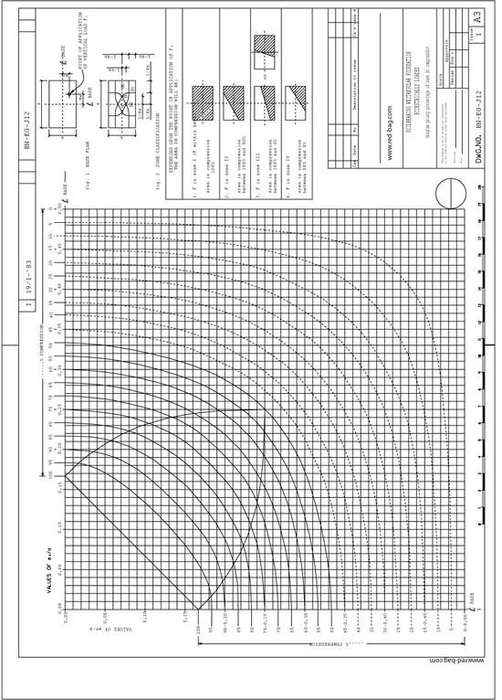
- Details
Table of Contents
- Introduction
- Scope
- General Procedure for flow diagram preparation
- The Process Flow Diagram
- The Pressure (P) - Temperature (T) Profile
- The Engineering Flow Diagrams (P&ID)
- The Utility Flow Diagram (UFD)
- The Interconnectiong Flow Diagram
- The Process Safeguarding Flow Diagram
- The Revamping Flow Diagram
- Check List
- Preparation of Line Table
- List of Related Red-Bag Standards
- List of Other Standards
- Typical Arrangement of Equipment Installation
1. Introduction
1.1 Purpose
The purpose of this document is to outline the procedures for the preparation of process flow diagrams, pressure-temperature profile diagrams, engineering, utility and interconnecting flow diagrams and special diagrams as revamp flow diagrams and pressure safeguarding flow diagrams.
1.2 Concept
Flow diagrams are highly specialized “language for information transfer. They represent the engineer’s concept of how plant equipment should be interconnected. The diagram is almost physical in a sense, since every piece of equipment, every pipeline, valve and instrument is shown. Diagrams are used to convey information between groups working on the project and translate the plant design into ‘real’ piping and equipment.
1.3 Use
By preparing the diagrams properly, the engineer can convey a great deal of technical information, quickly and accurately, with a Limited amount of paper work.
1.4 Tee of Diagrams There are 7 types of flow diagrams:
1.4.1 The Process Flow Diagram (PFD)
The PFD is developed by the Process Engineering Department. Final drafting by the Flow Diagram Squad. On this document are given the main process equipment, fluid flows, main control loops and critical valves. It is a tool for the process engineer(s) to convey information to project and specialist engineers to design the installation in detail (see fig: 6).
1.4.2 The Pressure Temperature Profile Diagram(PTP)
The PTP diagram is a document prepared by the Process Engineering Department with the purpose of providing project, control systems and piping engineers with the correct pressure and temperature correlations between the various piping systems, vessels, exchangers, etc. The document ensures that proper values are being used for preparation of data sheets, line tables and other documents as, e. g. painting systems, insulation, etc.
For PTP preparation procedures refer to Standard Specification BN-EG-UE-1 (Design guide for Pressure and Temperature profile).
1.4.3 The Engineering Flow Diagram (EFD)
On this document are shown all equipment connecting piping, utility piping, complete with control, loops and all other instrumentation, all valves a safety measures. It is the main tool for the project engineer to convey information to the piping design office and control systems engineering group for the detailed piping and control systems design (see fig: 13).
1.4.4. The Utilities Flow Diagram
This document. shows how utilities are generated and distributed from the source or supply point to the various parts of an installation. The diagram shows coon control loops, additional equipment that is deemed necessary to supply the utility as required and the safety measures necessary (see fig: 18). The diagrams shall be drawn in accordance with the geographical layout of the plant.
The diagrams are generally divided per generation activity, e.g. steam generation, inst air, cooling water, fuel oil, etc. The utility equipment shall be shown. Packaged units to be shown within, heavy dotted line.
1.4.5 The Interconnecting Flow Diagram (IFD)
These diagrams are prepared to show the interconnecting lines between various plant units and, e.g. tank farms, etc,
1.4.6 The Process Safeguarding Flow Diagram (PSFD)
This document shows the correlation of safety devices installed but indicated on separate EFD's. It “highlights” the final level of protection provided by the safety systems installed.
This document will be produced on client's request only, e.g. SIPM
1.4.7 Revamp Flow Diagram
“Revamping Flow Diagrams” shall be prepared to indicate which equipment, lines, control loops, etc. must be demolished, modified, removed or relocated, etc. in a revamping project. The existing engineering flow diagrams of a plant or unit to be revamped shall be used.
In general two sets of diagrams are to be prepared:
a) An updated existing EFD's version for demolishing purposes, RFD's.
b) New “as built” EFD's
For more details refer to Chapter 10.
1.5 Notes:
1.5.1 It must be noted that particular instructions given by client or licensor with respect to his requirements or special requirements covered by any authority decrees shall be observed.
1.5.2 If any of such rules, decrees or instructions exist, these must be mentioned in the “Project Specification”.
1.5.3 When these instruction have not been incorporated, the documents produced will be unacceptable to the client or licensor and/or authorities.
1.5.4 Where in the following text of this Engineering Procedure has been referred to other Company procedures or standards, this is only true where the Company standards are not conflicting with those mentioned under para 1.5.1.
1.5.5 To obtain maximum uniformity with regard to line thickness, lettering, symbols, etc. the drafting on vellums shall be executed by the Flow Diagram Squad.
1.5.6 There is still another flow diagram, prepared by the control systems engineering group, exclusively for use by process and control systems engineers. This flow diagram is principally a PFD on which the control system engineer indicates specific instrument physical data. The document is called; “Instrument Data Flow Sheet”. It is not further mentioned in this ‘Engineering Procedure”.
1.5.7 The examples presented in this Engineering Procedure are taken from actual jobs and include general Clients requirements. Therefore, the symbols used will not always be identical to the symbols shown on the legend sheet fig: 22.
1.5.3 On an EFD, a package unit, e.g. compressor, can be indicated with a heavy drawn block with reference to one or more vendor flow diagrams (process, lube oil, seal oil, water cooling, etc.) which can be adopted.
2. Scope
2.1 This Engineering Procedure shall be used as a standard for the preparation of process and engineer flow diagrams as outlined in para 1.4 of the Introduction.
2.2 It shall also be used to edit systematically the text for the Project Specification on the subject of flow diagram preparation.
2.3 The purpose of this Engineering Procedure is to provide the engineers with all necessary information to generate the various diagrams needed with the greatest consistency and efficiency possible.
(...)
The full procedure is available for registered users. The procedure is part of the Introduction and Basic Piping Design course at InIPED.
- Details
Table of Contents
- Orifice Plate Calculation
- Restriction Orifice Calculations
- Appendixes:
Appendix A, Calculation of Compressibility Factors
Appendix B, Flow Formula
Appendix C, Additional Specifications for Maximum Metering Accuracy
Appendix D, Conversion Formulae for Orifice Meters
Appendix E, Calculation of Meter Maximum Flow, When Orifice Bore Is Given
1. Orifice Plate Calculations
SCOPE : This standard gives instructions for the use of Company orifice plate calculation sheets :
- form B.N. -K003-1 (English Units)
- form B.N. -K003-2 (Metric Units)
GENERAL : The method of the orifice plate calculations mentioned above is based on: “Principles and practice of flow meter engineering” by
LK Spink, 8th edition, and is in accordance with AGA-ASME standards, and the AGA gas measurement committee reports numbers 2 and 3.
Moreover the draft ISO recommendation No. 532 (revised text) dated September 1964 has been used as a basis as well.
For a simplified description of the theoretical background see appendix B.
REFERENCES :
- Principles and practice of flow meter engineering L.K. Spink, 8th edition.
- Flow measurement with orifice meters R.F. Stearns, R.R. Johnson, R.M. Jackson, C.A. Larson published by D. van Nostrand Co. Inc.
- Gas measurement committee report No. 2 AGA, May 1935.
- Gas measurement committee report No. 3 AGA, April 1955, Reprint 1956).
- AGA flow constants (Foxboro)
- Draft ISO recommendation No. 532 September 1964.
INSTRUMENTATIONS : The instructions are numbered 1 to 30.
The same numbers appear on the calculation sheets for reference.
No. 1: FLUID: Fill in process fluid flowing through the orifice.
No. 2: MEASUREMENT UNITS: (see also note below)
Fillin the units of measurement in which the client requires the meter to read. These units should be agreed upon with the client and are generally specified in the applicable general specification for instrumentation. These units may be different from the units in which normal flow is given.
No. 3: BASE PRESSURE: (see also note below)
Fillin the common base pressure to which all measurements in the plant are referred. This again is to be agreed upon with the client.
Common accepted base, pressures are 14.70 psia, 760 mm Hg and 1 Kg/cm²A.
No. 4: BASE TEMPERATURES: (see also note below)
Fillin the common base temperature to which all measurements in the plant are referred.
Agreement with client necessary. Some accepted European base temperatures are:
- Liquid : 15°C or 60°F
- Gas : 0°C or 60°F
Note: See BN-SP-K1 Specification for Instrumentation.
No. 5: BASE SPECIFIC GRAVITY:
Fillin the specific gravity at base conditions as specified under Nos. 3 and 4. For liquids, the specific gravity is related to water, for gases to air. When working in metric units, liquid specific gravity is related to water at 15°C (density of water at 20°C is 0.99823 grams/cm³).
The specific gravity of gases can be obtained by dividing the molecular weight of the gas by the molecular weight of air (28.996).
For English Units the specific gravity is referred to water at 60°F.
No. 6: STEAM QUALITY:
Fillin quality of the steam, and when it is superheated or saturated, state this.
No. 7: NORMAL FLOW AT BASE CONDITIONS:
Fillin the normal flow at base conditions as specified and the units in which it is given.
No. 8: NORMAL FLOW IN WEIGHT UNITS:
Fillin the normal flow rate and the units in which this is given.
No. 9 and 10: METER MAXIMUM FLOW:
Fillin meter maximum flow after calculations as outlined under 27.
No. 11: MINIMUM FLOW:
If the minimum flow falls below 20% of the meter maximum flow, consideration should be given to the use of a second lower differential range instrument or a second orifice run.
No. 12: COMPRESSIBILITY:
Fillin the compressibility ratio’s Zb, Zf for gas flow which are defined as:
Zf = deviation from true gas law at operating conditions.
Zb = deviation from true gas law at base conditions.
The compressibility ratio’s can be determined from reduced pressure and reduced temperature as outlined in Spink, pages 351 and 352. See also appendix A.
No. 13: MOLECULAR WEIGHT:
Fillin molecular weight for gas flow only.
No. 14:OPERATING PRESSURE:
Fillin upstream pressure in psia or Kg/cm² Abs.
(Kg/cm²A = Kg/cm² gauge + 1.0336).
(PSIA = 14.70 + psig).
No. 15:OPERATING TEMPERATURE:
Fillin the operating temperature at the orifice in degrees Rankine for the English calculation sheet and degrees Kelvin for the metric calculation sheet (°R = °F + 459.6, °K = °C + 273.2).
No. 16: OPERATING SPECIFIC GRAVITY:
Fillin specific gravity at operating conditions. For liquids this specific gravity is referred to water of 60°F, when working in English units and 15°C when working in metric units.
No. 17: OPERATING DENSITY:
The operating density is in some cases to be found in tables such as the steam table but in other cases must be calculated as out-lined under 27.
No. 18 ABSOLUTE VISCOSITY:
The operating viscosity shall be given in centipoises. Viscosities of several liquids are given on pages 325 thru 331 of “Flow measurement with orifice meters” published by D. van Nostrand Co. Inc. or page 184 of “Principles and practice of Flow Meter Engineering” by L.K. Spink.
To convert from centistokes to centipoises multiply by the specific gravity. For other conversions see page 311 thru 324 of the Van Nostrand book.
No. 19: METER DIFFERENTIAL: (h)
A meter differential of 100 ins W.G., or its metric equivalent is preferable. To avoid swaging up higher ranges 150” W.G., 200” W.G., etc., may be used.
For compressible fluids, the range in inches water should be lower than the absolute static pressure, (at upstream side), this to keep the Y factor (see 29 III) within reasonable limits.
For computer calculations these values are:
- gas : (in H2O) = 1.3 upstream pressure
- steam : (in H2O) = 2 upstream pressure
No. 20: NOMINAL PIPE SIZE AND SCHEDULE:
Fill in the nominal size of the pipe, and the schedule (see piping specification).
If the pipe size is given to DIN standards, fill in outside diameter and the wall thickness. (When the form English units is used, state also the inside diameters in mm).
No. 21: ACTUAL I.D.:
The internal diameter as given in line tables and the square of this figure shall be stated in units as indicated.
When the form for English units is used, and the pipe is to DIN standards, fill in I.D. in inches, converted from I.D. in mm. stated in 20.
No. 22: CHART GRADUATION AND CHART FACTOR:
A chart graduation shall be specified preferably 0-10 or 0-100 square root.
This should be agreed upon with client. In special cases, a direct reading graduation may be used.
The chart factor is the rounded off meter maximum flow divided by the maximum chart reading.
No. 23: PRESSURE TAKE-OFF LOCATION:
When the static pressure measuring point has been specified, state if pressure is taken-off from upstream or downstream tapping. This in connection with the use of diagrams for expansion coefficient. (See 29, correction III).
It is Company’s standard practice to take off the pressure from the upstream tapping, as specified in the ISO standard no. 532 (Draft recommendation). Pressure measured at downstream tapping may be considered, when the static pressure is very low, so that the rule of thumb as mentioned is no. 19 page 7 can not be followed.
( ... )
The full procedure is available for registered users.
- Details
Table of Contents
1. Scope
This standard gives instructions for the use of Company control vale calculation sheet form BN-K 006.
2. General
The formulas and valve slide-rule are in accordance with the "Recommended voluntary standard formulas for sizing control valves", issued by the Fluids Control Institute with bulletin
F.C.I. 62-1.
However, temperature corrections have been added to these recommended basic formulas.
The valve sizing formulas have been based on the "U.S. VALVE FLOW COEFFICIENT CV", which is the yardstick of the valve capacity.
A valve flow coefficient CV is the number of U.S. gallons per minute of water at 40 to 120°F which will pass through a given flow restriction with a pressure drop of 1 psi.
The determination of the valve CV by the manufacturer should be based on Fluids Controls Incorporation, bulletin F.C.I. 58-2.
Because the CV coefficient is measured by the valve manufacturer at rather low pressure drops across the valve and at rather low static pressures the CV coefficient will be lower at higher pressure drops, depending upon the type of valve and design of the valve body.
Reference is made to booklet "The valve flow coefficient and its contribution in control valve sizing" and to the section "Limitations of valve sizing formulas", sheets 19 and 20.
European and especially German manufacturers sometime use a "Valve Coefficient KV ".
A valve flow coefficient KV is the number of cubic meters per hour of water at 5 to 30°C which will pass through a given flow restriction at a pressure drop of 1 kg/cm2.
Kv = 0.86 Cv and Cv = 1.17 Kv
A few valve manufacturers in Great Britan specify the CV valve coefficient based on an "Imperial gallon", instead of the U.S. gallon.
Cv (Imp. gpm) = 0.83 Cv(US gpm)
and Cv (US gpm) = 1.2 Cv(Imp. gpm)
The full procedure is available for registered users.
- Details
- General
- Formulae
- Instructions for the Use of Safety Relief Valve Calculation Sheet (General) Form BN-K008 10
- Instructions for Use of Safety Relief Valve Calculation, Attachment “A”
(External Fire) Form BN-K009 - Instructions for Use of Safety Relief Valve Calculation, Attachment “B”
(Heat Exchangers) Form BN-K010 - Instructions for Use of Safety Relief Valve Calculation, Attachment “C”
(Miscellaneous) Form BN-K011
Appendix A - Calculation of Latent Heat of Evapourization
Appendix B - Calculation of the Maximum Duty of a Heat Exchanger
Appendix C - Derivation of API-ASME Code Formula
Appendix D - Formulae for Safety Valve Calculation in Accordance with German Rules (TÜV and AD-Merkblatt A2)
Appendix E - Comparation between API-Code Rumanian-Code for the Calculation of Pressure Relieving Valves
Appendix F - Comparation between API-Code and the Italian-Code for the Calculation of Pressure Relieving Valves
1. General
1.1 Scope
This standard has been developed to standardize the method of safety relief valve calculations in accordance with API, ASME codes and local codes.
1.2 Calculation Sheet
For the calculation of a safety relief valve, the following standard calculation forms can be used:
BN-K008 : Safety relief valve calculation
BN-K009 : Attachment “A” (External fire)
BN-K010 : Attachment “B” (Heat exchangers)
BN-K011 : Attachment “C” (Miscellaneous)
The main safety relief valve calculation sheet, form BN-K008 has been developed to evaluate the governing hazard and to calculate the area of the relief valve.
The attachments have been designed to evaluate the quantity which has to be relieved by the safety relief valve.
1.3 References
1. API Recommended Practice for the design and installation of pressure relieving system in refineries, API RP 520, second edition, Sept. 1960.
2. The design and construction of pressure relieving systems by Nels E. Sylvander and Donald L. Katz, April 1948.
3. Data Handbook on Hydrocarbons by J.B. Maxwell, 5th edition.
4. Engineering Data Book by the National Gasoline Supply Men’s Association (NGSMA), 7th edition 1957.
5. Chemical Engineers’ Handbook, John H. Perry, 3rd edition, 1950.
1.4 Definitions
Safety valve
An automatic pressure relieving device actuated by the static pressure upstream of the valve, and characterized by rapid full opening or pop action. It is used for stream, gas, or vapor service.
Note: This type of valve is normally not specified by Company.
Relief valve
An automatic pressure relieving device actuated by the static pressure upstream of the valve, which opens in proportion to the increase in pressure over the opening pressure. It is used primarily for liquid service.
Note: This type is normally only used in the size 3/4” x 1” or 1” x 1” for thermal expansion.
Safety relief valve
An automatic pressure actuated relieving device suitable for use as either a safety or relief valve, depending on application.
Note: This type is used for general applications.
Set pressure
- Liquid service:
for a relief or safety relief valve on liquid service, the set pressure, in pounds per square inch gauge, is to be considered the inlet pressure at which the valve starts to discharge when discharging against atmospheric conditions. - Gas, vapor or steam service:
for a safety relief valve on gas, vapor or steam service, the set pressure, in pounds per square inch gauge, is to be considered the inlet pressure at which the valve pops when discharging against atmospheric conditions.
Popping pressure
Same definition as set pressure for gas, vapor or steam service, when discharging against back pressure. (Pressure at which the valve pops when in use.)
Differential test pressure
The pressure differential in pounds per square inch between the set pressure and the constant superimposed back pressure.
It is applicable only when a conventional type safety relief valve is being used in service against constant superimposed back pressure.
Net spring setting
Same definition as for differential test pressure.
Cold differential test pressure
The set pressure or the differential test pressure at which a safety relief valve must be set on cold fluid on a test drum plus a predetermined increase in the cold fluid setting, in pounds per square inch, that will result in the valve opening at the correct set pressure in service when the actual service temperature is higher than that of the cold fluid which is used in the test drum. This is the pressure at which the valve should be set on repair shop testing facilities.
Note: The difference in cold and hot setting is the result of change in characteristic of the spring.
Cold net spring setting
Same definition as for cold differential test pressure.
Operating pressure
The opening pressure of a vessel is the pressure in pounds per square inch gauge, to which the vessel is usually subject in service. A vessel is usually designed for a maximum allowable working pressure, in pounds per square inch gauge, which will provide a suitable margin above the operating pressure in order to prevent any undesirable operation of the relief device. (It is suggested that on processing vessels this margin be approximately 10 percent, or 25 psi - whichever is greater.)
Note:
- Take care for reciprocating engines, where peak pressure might reach the set pressure of the valve.
- When setting closer to the operating pressure is required, pilot operated safety valves or “0” ring seal might be considered.
Design pressure
The gauge pressure at which the vessel has been designed.
Note: Safety relief valves are usually set at this pressure.
Maximum allowable working pressure
The maximum gauge pressure, at the coincidental design temperature, permissible at the top of a vessel in its operating position, and which could be the basis for the upper limit in pressure setting of the safety relieving devices for any specific operation.
Note:
- When designing a vessel, the calculations will result in a material thickness. This thickness is rounded off to the first higher thickness which is commercially available. Recalculation of the vessel using actual plate thickness will result in a maximum allowable working pressure which is usually higher than the design pressure.
- Usually recalculation is not done (difference in plate thickness is low for European standards), in that case maximum allowable working pressure is equal to the design pressure.
Overpressure
Pressure increase over the set pressure of the primary relieving device is overpressure. It is the same as accumulation only when the relieving device is set at the maximum allowable working pressure of the vessel.
Accumulation
Pressure increase over the maximum allowable working pressure of the vessel during discharge through the pressure relief valve, expressed as a percentage of that pressure, or pounds per square inch, is called accumulation.
Notes:
- For European plants, it is usual to take an accumulation of 10% . For American plants a value of 20% may be taken for external fire. 25% for liquid relief and in all other cases 10%.
Blowdown
Blowdown is the difference between the set pressure and the resealing pressure of a pressure relief valve, expressed as percentage of the set pressure, or pounds per square inch.
Note: A blowdown between 4% and 5% is usually specified. Care is to be taken that the inlet piping does not have a total pressure loss in excess of 3%. The total pressure loss shall include the velocity head loss ( 1/2 rV2). Note however, that the friction loss should not exceed 1% and the velocity head loss should not exceed 2% of the allowable pressure for capacity relief.
Lift
The rise of the valve disc in pressure relief valve when the valve disc moves from the closed position is called lift.
Back pressure
Pressure on the discharge side of a pressure relief valve.
- Constant back pressure:
back pressure which does not change appreciably under any condition of operation whether or not the pressure relief valve is closed or open. - Variable back pressure:
back pressure which develops as a result of the conditions outlined below.
a) Built-up back pressure: variable back pressure as a result of flow through discharge piping after a single pressure relief valve starts to open.
b) Superimposed back pressure: variable back pressure that is present before the pressure relief valve starts to open.
Note: Variable back pressure on conventional safety relief valves shall never exceed 10% of the gauge set pressure.
Variable back pressure on bellow seal safety relief valves shall never exceed 50% of the absolute set pressure as that is the limit for critical flow, on which the formulae are based.
Coefficient of discharge
Correction factor for the nozzle area, due to contraction etc., include all deviations from ideal flow through the nozzle.
Note:
For full lift safety relief valves, this factor is usually 0.97.
For relief valves at 25% accumulation: 0.64.
For relief valves at 25% accumulation: 0.64.
These low coefficients correct also for the reduction in area which occurs at lower lifts of the disc above the seat.
General rules for the use of safety relief valves
Following, a few general rules will be given for the application of safety relief valves. These rules are only to be used as a guidance.
Safety relief valves are required:
- On all vessels containing fluids which may vaporize when the vessel is subject to fire.
- On all vessels where a closed outlet valve may cause an over pressure.
- On all reciprocating pumps and compressors, if not protected internally.
- On the outlet of turbines, where the design pressure of the low stage casing is lower than the inlet pressure.
- On all distillation and fractionating towers where reflux or cooling water failure may cause excessive vaporization.
- On heaters and furnaces where low flow may cause cooking.
- On heat exchangers or heaters where the cold medium may be blocked.
- On all storage tanks, not vented to atmosphere, where vapor pressure or pumping may cause over or under pressure. In this case special combined pressure vacuum relief valves are to be specified. (Breather valves).
- 3. In cases of long lines, containing liquid, which may be blocked when exposed to the sun (for example butane, propane).
- 4. In all cases where a volatile liquid may get into a vessel under conditions that it vaporizes where the vessel is not designed for the vapor pressure.
- In cases where non-condensable accumulate in a condenser, decreasing the efficiency, so that a pressure rise may occur.
- Tube failure in heat exchangers, which may cause vaporization, or excessive pressure on the shell.
- Control valve failure or instrument failure which either results in one of the hazards 1 through 12, or in any other hazard as for example a reducing station, failing in the open position.
Notes:
- Where more vessels are connected, so that they cannot be separated by block valves, they are to be considered as one system. (Except when local codes imply separate valves.)
- In cases where equipment has to be protected against two or more of the above mentioned hazards, the safety valves shall be calculated for the condition causing the highest flow rate to be relieved, thus assuming that only one hazard will occur at the same time. (Single risk concept.)
- It is evident that when a hazard is the result of another hazard, both hazards are to be taken into account.
2. Formulae
Below a summary of formulae has been given. Most of these formulae already appear on the calculation sheet, but this summary also gives some other formulae which are to be used in special cases.
The formulae given on the calculation sheet for evaluation of nozzle area for vapors is a safe approximation: when accurate calculations are to be made, formula number 2 has to be used in which the “C” factor can be evaluated from formula 2A, or from Binder IV with curves and tables.
Formula 4 gives the nozzle are for steam when the safety valve has to be calculated as per ASME boiler code. Formula 10 gives a quantity of thermal expansion when no normal size is taken. See 68, liquid expansion.
In each formula for vapors the super compressibility factor (Z) can be included as a multiplier of the absolute temperature (also under the square root sign).
This will result in a smaller valve size.
Leaving it out always gives a safe approximation.
SUMMARY OF FORMULAE
UNITS OF MEASUREMENT
| DESCRIPTION | ENGLISH UNITS | METRIC UNITS | NO. |
| RELIEF QUANTITY VAPOURS (GENERAL PURPOSE) |  |
 |
1 |
| RELIEF QUANTITY VAPOURS (ACCURATE) |  |
 |
2 |
| CONSTANT BASED ON k (C OR C') |  |
C'=4.81 x C | 2A |
| RELIEF QUANTITY STEAM (GENERAL PURPOSE) |  |
 |
3 |
| RELIEF QUANTITY STEAM (ASME BOILER CODE) |  |
 |
4 |
| RELIEF QUANTITY LIQUID (INCLUDING VISCOSITY CORRECTION) (NOT FOR BALANSEAL VALVES) |  |
 |
5 |
| VAPOURATION WITH CONDENSATION |  |
 |
6 |
| VAPOURATION WITHOUT CONDENSATION |  |
 |
7 |
| CONSTANT Y |  |
 |
7A |
| SPLIT TUBE (NO VAPOURIZATION) |  |
 |
8 |
| SPLIT TUBE (VAPOURIZATION) |  |
 |
9 |
| THERMAL EXPANSION |  |
 |
10 |
| RELIEF QUANTITY LIQUID (INCLUDING VISCOSITY CORRECTION) (FOR BALANSEAL VALVES ONLY) |  |
 |
11 |
|
FORMULAE IN METRIC UNITS, GIVING AREA IN CM2
|
||
RELIEF QUANTITY VAPORS (GENERAL PURPOSE)  |
1A | |
RELIEF QUANTITY STEAM (GENERAL PURPOSE)  |
3A | |
RELIEF QUANTITY LIQUID  |
5A | |
The full procedure is available for registered users.
- Details
Preparation of Equipment Classification Lists for the PED Authority
Table of content
- Purpose
- General
2.1 Classification Lists
2.2 Pressure Vessel Authority for the Netherlands - Responsibilities
- Guide Lines
4.1 Data Supply and Handling
4.2 Status of the Equipment Classification List in the Netherlands
4.3 Forms, Units, Language and Document Numbering
4.4 Details per Classification List Column
4.5 Other Notes
4.6 Further Handling of the Classification List - Flowchart
- References
- Attachments
1. Purpose
The purpose of this guide line is to describe how the equipment classification list, required for submission to Stoomwezen B.V in the Netherlands, shall be completed with relevant data.
2. General
2.1 Classification Lists
A general guide line on equipment classification lists for pressure vessel authorities is contained in ref. 6.4. It describes the process that should lead to conclusions regarding the required nature and level of pressure vessel inspection by authorities or designated third parties.
2.2 Pressure Vessel Authority for the Netherlands
The pressure vessel authority for the Netherlands is Stoomwezen B.V. This is the sole organization, that can approve and stamp equipment classification lists for Dutch projects. For piping, the classification is normally shown in the line designation tables; these are then subject to Stoomwezen B.V. approval in the same way.
3. Responsibilities
The Project Manager has the overall responsibility for the control of the prepararation and the approval of the classification list for projects in the Netherlands.
The Project Engineering group has the responsibility for the preparation of the classification list for projects in the Netherlands.
The Authority Engineering group has the responsibility for checking the contents of the classification list, for determining the classifications and further handling of the list for projects in the Netherlands.
These responsibilities are worked out in more detail in ref. 6.4.
4. Guide Lines
4.1 Data Supply and Handling
Ref. 6.4 gives guidance for the supply and the checking of equipment classification list data and describes a number of handling aspects of this list.
4.2 Status of the Equipment Classification List in The Netherlands
The equipment classification list in the Netherlands is a document which requires formal approval by Stoomwezen B.V. for every issue. After approval, it is normally stamped for concurrence only, which does not imply responsibility for Stoomwezen B.V. for its contents.
Certain activities such as the submission of Stoomwezen application forms for equipment and piping can not start if there is no formally approved classification list.
4.3 Forms, Units, Language and Document Numbering
4.3.1 Basic Form
The handwritten basic form used by Company for a Dutch equipment classification list is shown in Attachment 3 of this guide line. The column numbers 1 through 21 have been added for easy reference. It shall be noted that the form deviates slightly from the requirements set forth in ref. 6.7.
Some clients (e.g., Exxon Chemicals) still prefer to use have their own basic form, even if not in accordance with ref. 6.7; such forms may have less or even more columns.
When a computerized form is used (for example, in dBase III software, see Attachment 4) a certain flexibility will be possible in the presentation and any deviations from ref. 6.7 can be agreed with Stoomwezen B.V. per project. Due to computerizing, the form can also be made suitable for other (internal) Badger purposes by adding further columns.
A completed version of a handwritten classification list is shown in Attachment 5.
4.3.2 Units
Pressures are indicated in "Bar" and understood as "Bar(g)", which equals Bar(abs) minus one. Full vacuum is indicated as '-1' (bar), although the use of the abbreviation 'FV' is not prohibited.
Older equipment classification lists often show pressures in kg/cm2. They can be converted to bar on a 1:1 basis while ignoring the difference between the units.
Temperatures are always given in degrees Celsius. Volumes are indicated in cubic meters (m3) or cubic decimeters (dm3). Densities, if filled out, are indicated in kg/m3; they are used for the hazard category calculations (ref. 6.5 and 6.8).
4.3.3 Language
The language on the equipment classification list is normally Dutch, but the use of English is accepted by Stoomwezen B.V.
4.3.4 Document Numbering
For document numbering see ref. 6.4.
4.4 Details per Classification List Column
The column numbers refer to the manual form shown in Attachment 3. The computerized form misses columns 4, 12, 15 and 21 for space reasons or because they are less useful.
4.4.1 Columns 1, 2, 4, 6 and 21 (Equipment number, P&I diagram number, number of pieces, manufacturer, remarks)
The columns 1, 2, 4, 6 and 21 are self-explanatory. Column 4 is rarely used any more and, consequently, left out on the computerized form; instead, all individual items are listed.
4.4.2 Columns 3 and 5 (Registration Number, Serial Number)
The columns 3 and 5 must be advised by Stoomwezen B.V. after approval of the filled out data; both numbers serve administrative purposes.
Notes:
- The Client may state his own serial number, but this number has to be approved by Stoomwezen B.V.
- The registration numbers have to be obtained from the manufacturer's documents; these numbers are normally shown in the approval letter from Stoomwezen B.V. or the Nieuw Bouw Rapport (NBR) for the equipment.
- A piece of equipment receives only one registration number, irrespective of the number of spaces the equipment has.
4.4.3 Column 7 (Substance and Phase)
In column 7 the names of the substances and their phases shall be stated. Mixtures should be described in sufficient detail for assessing the effects of each component (see also 4.5.3).
Notes:
For definitions of the phases: see Attachment 1 ("phase" is not identical with the concept "phase" in physics).
- For vessels without tubes only the shell side data shall be filled out.
- For heat exchangers both shell and tube side data shall be given. Reactors etc. consisting of one shell with internal separation walls are considered as one vessel, the data shall be specified for all individual spaces because the classification will be determined by the space with the highest requirements. In all these cases, an additional line per equipment item is required, because the majority of data will be different for the two (or more) spaces. For discussion of spaces, see Attachment 1.
4.4.4 Column 8 (Hazard Category)
In column 8 the hazard category shall be indicated. The hazard categories of shell and tube sides of heat exchangers as well as other individual spaces within the same shell may be different.
Notes:
For the hazard category calculation procedure, see ref. 6.8; for practical hints, see ref. 6.5.
4.4.5 Column 9 (Boiling Point at 1 Bar(abs))
In column 9 the boiling point at 1 bar(abs) shall be stated. For mixtures, the lowest temperature of the boiling range should be taken.
Notes:
- For a sublimating solid, the temperature at which the sublimation starts should be stated.
- The remark on mixtures refers to the most common type of mixtures, i.e. mixtures of liquids only.
For other cases such as a solid/liquid mixture, the lowest temperature at which the liquid starts boiling should be regarded as the boiling temperature. - For special or complex cases, e.g. involving a decomposition reaction, the Authority Engineering group should be contacted.
4.4.6 Column 10 (Vapor Pressure)
Column 10 shall indicate the vapor pressure at the permitted temperature (see 4.4.10). For mixtures the vapor pressure is the sum of the partial vapor pressures of the components. The vapor pressure can never be higher than the set pressure of the pressure safety device protecting the equipment or equipment part.
4.4.7 Columns 11 and 14 (Normal Operating Pressure and Temperature)
Columns 11 and 14 shall state the normal operating pressure respectively temperature.
Notes:
- These values should preferably in accordance with the process flow scheme(s), if these are submitted (see ref. 6.3).
- Client's forms sometimes do not state this information.
- For exchangers and other equipment with varying temperature either the range of temperatures should be shown, or the highest temperature only. Pressure variations can usually be ignored unless they are extreme.
Column 12 (Permitted Working Pressure)
Column 12 shall state the permitted (working) pressure. This is the pressure at which a piece of equipment may be used jointly with the installation in which it is placed.
The permitted pressure usually equals the pressure for which the equipment is protected, or, in case of a pump discharge without protection, the pump shut off pressure. The permitted pressure is the pressure which will be stated on the license.
Notes:
- The permitted pressure shall be understood as "maximum possible operating" pressure. The word "permitted" is used from the view point of the license and in this sense, permitted equals allowable.
- Newer types of the basic form, in particular the computerized ones, do not contain this column any more. The function of this figure (preventing that too high pressures will be licensed) is for most cases fulfilled by the design pressure. See 4.4.9.
Column 13 (Design Pressure)
Column 13 shall indicate the design pressure, which should be equal to or higher than the permitted pressure. The design pressure will be stated on the "Bewijs van Onderzoek en Beproeving"(BOB, certificate of examination and pressure testing), and is the pressure for which the equipment or the equipment part will be assessed by Stoomwezen B.V.
Notes:
- If no permitted pressure is specified, the license will use the design pressure as such. By doing so, the often difficult discussion regarding the 'maximum possible operating pressure' is avoided.
- The concept 'maximum possible operating pressure' is mainly useful for cases where the design pressure specification has other reasons than the process conditions only. An example are the design pressures for a Claus-type sulfur recovery unit.
- For each single space only one design pressure should be specified (so, for a column no difference between top and bottom design pressure). Any static effects should be taken into account in the manufacturer's design calculations.
- Ref. 6.1 and 6.2 should be applied when determining design pressures.
Column 15 (Permitted Temperature)
In column 15 the permitted temperature shall be indicated. The permitted temperature, which usually equals the maximum operating temperature, is the temperature which will be stated on the licence.
Notes:
- The permitted temperature shall be understood as "maximum possible operating" temperature. The word "permitted" is used from the view point of the licence and in this sense, permitted equals allowable.
- Newer types of the basic form, in particular the computerized ones, do not contain this column any more. The function of this figure (preventing that too high temperatures will be licensed) is for most cases fulfilled by the design temperature. See 4.4.11.
Column 16 (Design Temperature)
In column 16 the design temperature shall be indicated, which should be equal to or higher than permitted temperature. The design temperature will be stated on the "Bewijs van Onderzoek en Beproeving" and is the temperature, for which the equipment part will be assessed by Stoomwezen B.V.
Notes:
- If no permitted temperature is specified, the license will use the design temperature as such. By doing so, the often difficult discussion regarding the 'maximum possible operating temperature' is avoided.
- The concept 'maximum possible operating temperature' is mainly useful for cases where the design temperature specification has other reasons than the process conditions only.
- For each single space only one design temperature should be specified (so, for a column no difference between top and bottom design temperatures). The effect on the wall thickness calculation is normally not large enough to enter into a long discussion with Stoomwezen B.V. which may, at its conclusion, not lead to the planned result.
- Ref. 6.1 and 6.2 should be applied when determining design temperatures.
Column 17 (Volumetric Capacity)
Column 17 should state the volumetric capacity for each space (e.g. shell and tube side). If not stated on the process data sheet this figure should be estimated based on - sometimes assumed - sizes, or, preferably, be obtained from the Vessel Engineering group.
All volumetric capacities should be verified with the manufacturer's documents as part of the regular updating of the classification list; this is particularly applicable to shell and tube heat exchangers and air coolers, with which the largest deviations from the estimated values are experienced.
Column 18 (Classification)
The Authority Engineering group shall determine the classification by means of Attachment 2 of this guide. The most common categories found are (1) steam or vapor equipment (either boiler or vessel - categories SK, DK, SV and DV) and (2) non steam-act pressure vessel (category DR). The classification is assessed for each space of the equipment.
The final classification is derived from the most severe set of design conditions for the different spaces; as a consequence, a water cooled heat exchanger can become classified as a 'vapour vessel' due to the conditions of the non-water side. See also 4.5.
The requirement for a license is usually determined by the Authority Engineering group; Stoomwezen B.V., however, may have a different opinion and will advise see by means of commenting on the classification list. The requirement for a BOB per condition of the Environmental permit should be determined by the Authority Engineering group.
For cases where a BOB is not possible (e.g. storage tanks) a BvK ("Bewijs van Keuring", certificate of inspection) or a VGB ("Verklaring van Geen Bezwaar", statement of no objection) can be requested.
Column 19 (Pressure Protection)
In column 19 the safety valves or rupture discs protecting a piece of equipment should be stated with set pressure and seat diameter. For rupture discs the nominal diameter and the nominal bursting pressure should be indicated.
Notes:
- In the first issue of the classification list it is usually only possible to indicate the valve item numbers and the set pressures.
- The set pressures and the back pressure of the safety valves need to be reviewed in an early stage of the project to avoid equipment design pressure changes in a later stage. For example, problems may occur when a safety valve in liquid service is located at some height above the protected equipment. See also ref. 6.1/6.2.
- In practice, only the safety valves on or very near to the equipment protected are listed; more remotely located safety valves should be reviewed with the Authority Engineering group before listing (example : sometimes a safety valve for a vessel is located downstream a directly connected heat exchanger rather than upstream of it; a survey of the complete circuit is then necessary to see what is protected by the subject safety valve).
Column 20 (Part)
In Column 20 the equipment part for which the data apply, should be indicated (e.g. for towers: top respectively bottom - see Attachment 4 gives an example). As noted above (see 4.4.9 and 4.4.11) this information is nowadays considered less useful. The computerized form does not contain a column to indicate the part, but if necessary a remark can be added.
Other Notes:
Equipment with More than one set of Operating Conditions
Equipment that may be subject to different operating conditions within the normal processing sequence (for example, regenerable reactors or vessels in multi-purpose plants) should be described with an additional line in the classification list. This will satisfy Stoomwezen B.V., that all possible operating conditions have been reviewed and that the final classification is in accordance with the most severe set of conditions found.
Equipment with Temporary Operating Conditions
Equipment with temporary operating conditions (for example, towers with steam out conditions) should only be marked as such, if these conditions may effect the classification. So, if the steam out pressure is limited to 0.5 barg or less, no separate mark should follow, because it does not change the classification nor does it cause Stoomwezen B.V. assessment or inspection work. Ref. 6.7 specifies the lower limits of this assessment or inspection work.
Temporary operating conditions should, in general, not be indicated on flow diagrams and similar documents, unless they are the result of a specific operational requirement and permanent provisions for their use (connections, controls etc.) will be installed. So, activities like regeneration, coke burning or run different processes in the same (or partially the same, such as for multi-purpose plants) installation are to be indicated on flow diagrams. Steaming out, on the other hand, is normally a maintenance activity, for which no permanent connection to the steam system is provided and should not be indicated on flow diagrams.
Special Requirements of Stoomwezen B.V.
In a number of cases Stoomwezen B.V. may comment on the design conditions chosen. This is e.g. the case with equipment, that is installed in the open air (thus, subject to the weather conditions inclusive of low temperatures) and can be put out of operation, but kept under pressure. The possible occurrence of such cases should be carefully reviewed during the early stages of engineering to avoid late comments and possibly material selection consequences. Other more or less frequent discussion points are the effects of substances such as hydrogen and hydrogen sulfide on the material.
Further Handling of the Classification List
The further handling of the classification list includes, amongst others, the following activities (see also ref. 6.4):
Checking for completeness.
Preparing for issue.
Submittal of issued classification list to Stoomwezen B.V.
Evaluation and incorporation of comments received from Stoomwezen B.V.
Updating the classificiation list with new and revised data.
Advising the interested parties such as the Vessel Engineering group and the Project Engineering group on comments affecting the equipment c.q. the requirements imposed on the manufacturers.
5. Flowchart
6. References
Document
| Number | Title | Level |
| BN-EG-UE | Pressure Temperature Profile | 5 |
| BE-EG-UE2 | General Rules to Establish Mechanical Design Pressures and Temperatures |
5 |
| BN-EG-UE203 | Defining Information to be Submitted to Pressure Vessel Authorities | 5 |
| BN-EG-UE204 | Classification Lists for Pressure Vessel Authorities | 5 |
| BN-EG-UE216 | Practical hints for Hazard Category Calculations | 5 |
| G-0201 | Stoomwezen Rule "Definitions; Quantities, Units and Symbols" | - |
| G-0402 | Stoomwezen Rule "Classification of Pressure Vessels" (Classification List) | - |
| G-0701 | Stoomwezen Rule "Hazard Categories" | - |
7. Attachments
- Definitions of Terms and Concepts for use in the Netherlands.
- Classification of Pressure Vessels in the Netherlands.
- Basic form for manually filled out Classification Lists for the Netherlands.
- Example of Computerized and filled out Classification List for the Netherlands (without columns for revision number and remarks).
- Example of manually filled out Classification List
1. Definitions of Terms and Concepts for Use in the Netherlands
The following definitions are given to clarify the terminology of the classification lists for Stoomwezen B.V. and the underlying concepts. A detailed overview is given in ref. 6.6; the text below emphasizes the most important definitions in general wording.
1.1 Phases
Liquid: Any substance in the liquid phase.
Vapor: The gas phase resulting from the heating of a liquid; if the liquid is water, the vapor is commonly called 'steam'.
Note:
The liquid phase of a substance with a critical temperature equal to or lower than 45°C is never considered as heated; the gas phase of such substance can therefore never be a vapor, but is a gas. For heating see 2, below.
- Gas: Any substance in the gas phase other than vapor.
1.2 Heating
Steam apparatuses and vapor apparatuses are considered to be heated when the working temperature exceeds 45 degrees.
Note:
Heat transfer in such apparatuses at a working temperature above 45 °C always involves heating.
1.3 Pressure Vessels/General
- A pressure vessel is a technical device intended to keep up a pressure differential. This definition includes boilers.
Note:
This is a very wide definition; for further details and definitions used outside the Netherlands see ref. 6.5. - The pressure section is that part of a pressure vessel that directly maintains the pressure differential.
The pressure section encloses one or more spaces. It also includes the walls etc., that maintain a pressure differential between two spaces, as well as connected nozzles, flanges and fasteners. Supports etc., are part of the pressure vessel, but not of the pressure section. - Appurtenances: technical devices serving to make possible the use of a pressure vessel or system or to promote its safe use.
Appurtenances accordingly comprise valves, level indicators, pressure protection, pumps, pressure gauges, blow-off cocks, feed apparatus, controllers etc.
1.4 Pressure Vessels/Details
Steam boiler: An apparatus in which water is heated by heat supply which is not derived from another apparatus to which the Steam Act is applicable.
Note:
This definition would imply, that e.g. a waste heat boiler located downstream a reactor would generally be classified as a steam or vapor boiler, despite the fact that a waste heat boiler has rarely a boiler management system. This situation should, wherever possible, have an impact on the safety valve installation only and be limited for e.g. inspection terms by Stoomwezen.
Steam apparatus: A steam boiler or apparatus which is connected to the former in such a way that heat transfer takes place between the apparatus and the steam boiler by means of vapor or liquid.
Vapor boiler: An apparatus in which a liquid other than water is heated by heat supply which is not derived from another apparatus to which the Steam Act is applicable.
Vapor apparatus: A vapor boiler or apparatus which are connected to the former in such a way that heat transfer takes place between the apparatus and the vapor boiler by means of vapor or liquid.
Vessel: A steam apparatus other than a steam boiler or a vapor apparatus other than a vapor boiler.
Pipeline: A pressure vessel which serves mainly for the conveyance of substances; they may be split into (1) installation lines and (2) transmission lines, i.e. pipe lines connecting installations or facilities without being part of it.
Storage Tank: A pressure vessel intended for the storage of liquids below their atmospheric boiling point and not being part of a processing installation.
Note:
As a consequence, pressurized storage vessels (spheres, bullets) are not storage tanks.
Non-Steam Act Pressure Vessel: A pressure vessel which does not belong to one of the following categories:
- Steam or Vapor Apparatus
- Gas Cylinder or Transport Tank
- Storage Tank
- Pipelines
- Machine Parts
- Pressure Vessels containing solely a liquid below its atmospheric boiling point.
Notes
- Vessels and non-steam act pressure vessels together correspond approximately to the English concept "unfired Pressure Vessels".
- The above as well as other definitions are described in ref. 6.5.
1.5 Pressure Vessels/Separate Sections
The following shall be regarded as a separate section (space) of a steam apparatus or a vapor apparatus:
- A space which is neither directly nor indirectly connected to another space of the steam apparatus or vapor apparatus.
- A space which is connected to another space of the steam apparatus or vapor apparatus by means of openings in the common wall of the two spaces having a total crosssectional area of passage not exceeding 20 cm2.
- A space which is connected to another space of the steam apparatus or vapor apparatus by means of pipes with an average length of at least ten times the diameter of the circle with an area equal to the total cross sectional area of passage of the pipes.
If the wall between two spaces is such that it must be expected to collapse when the working pressure is exerted on only one side, these spaces shall be considered together as a single space of the steam apparatus or vapor apparatus, irrespective of the preceding statements.
Classification of Pressure Vessels (Netherlands only)
