
")
- Details
The engineering guides are intended for executing work such as engineering calculations, prepare reports or preparing engineering documents. These guides are usually not part of the auditable section of the QA system. The focus of the guides is primarily related to project execution because the procedures are written from the perspective of an Engineering Contractor.
The below listing gives an indication of the available procedures. Use Library Menu navigation bar at the left to view the public procedures on this website or use this link to go directly to the QA system documents >
| Number | Title |
| BN-EG-J11 | Civil Specifications to be Incorporated In Requisitions for Reinforced Concrete Stacks |
| BN-EG-J12 | Soil Bearing Rectangular Foundation Eccentrically Loaded |
| BN-EG-K1 | Limitation of Control Valve Noise |
| BN-EG-K2 | Standard Method for Orifice Calculations |
| BN-EG-K3 | Standard Method for Control Valve Calculations |
| BN-EG-K4 | Standard Method for Safety Relief Valve Calculations |
| BN-EG-UE001 | Engineering Design Guide Pressure Temperature Profile (PTP) |
| BN-EG-UE002 | General Rules to Establish Mechanical Design Pressures and Temperatures |
| BN-EG-UE003 | Engineering Design Units of Measurement |
| BN-EG-UE101 | Process Close-Out Reports |
| BN-EG-UE102 | Trayed and Packed Tower Inspections |
| BN-EG-UE103 | Seminar Reporting |
| BN-EG-UE104 | Recording Telephone Conversations |
| BN-EG-UE105 | Execution of a HAZOP Study |
| BN-EG-UE106 | Production of a Hazardous Materials Properties List |
| BN-EG-UE109 | Guide for Vessel Sizing |
| BN-EG-UE203 | Defining Information to be Submitted to Pressure Vessel Authorities or Designated Third Party Organizations |
| BN-EG-UE204 | Preparation of Equipment Classification Lists for Pressure Vessel Authorities |
| BN-EG-UE205 | Preparation of Pump Lists for Pressure Vessel Authorities |
| BN-EG-UE206 | Nader Onderzoek by Stoomwezen |
| BN-EG-UE207 | Fabrication and Erection of Stoomwezen Piping |
| BN-EG-UE208 | Preparation of Engineering Flow Diagrams |
| BN-EG-UE214 | Preparation of Equipment Classification Lists for the PED Authority |
| BN-EG-UE220 | Guide on Four Major CE-marking Guidelines per Account Code |
| BN-EG-UE306 | Procurement of Design Models |
| BN-EG-UE308 | Safety Instrumented Systems and Reliability Analysis, Engineering Guide for |
- Details
Table of contents
- Scope
- Definition and Purpose
- Responsibility
- Data to Be Indicated on a PTP
- The PTP Development
- Distribution and Use of PTP's
1. Scope
Reference: engineering design guide BN-EG-UE002: general rules to establisch mechanical design pressure and temperature. Appendix a to BN-EG-UE002: Applicable rules in various countries.
1.1 This Engineering Design Guide shall be used for the preparation of Pressure Temperature Profiles (PTP). It is not intended as a complete guide to the interpretation of the several codes for the design of pressure vessels or of piping which apply in various countries.
1.2 This Engineering Design Guide shall be used in conjunction with the documents with establish the code and contractual criteria applicable to the design of the plant.These documents are e.g.:
- the project procedure manual with basic engineering design data (including a definition of design pressure and temperature), - applicable codes for pressure parts,
- clients standards,
- clients insurer’s requirements.
2. Definition and Purpose
2.1 A pressure Temperature Profile is a simplified flow diagram on which the various possible process operating and design conditions have been indicated.
2.2 The purpose of a PTP is:
- to serve as internal check device for use by the Process Department to verify pressures and design temperatures for each plant component (equipment and lines) are consistent and in accordance with all applicable code requirements and job specifications under all possible operation conditions during start-up, normal operation, regeneration, on-stream cleaning, planned-or emergency shut-down, malfunctioning or maloperation.
- to established or verify the location, the set-pressures and the relieving temperature of safety valves in order to ensure a safe plant design in accordance with the code requirements and job specifications under all possible conditions.
- to show, if required, to the authorities that the correct design conditions have been established and that adequate protection against overpressure or vacuum and over- temperature has been provided.
- to serve as one of the process documents used by Design Engineering in the execution of the design.
- to assist Project Engineering Department in the preparation of line designation tables.
2.3 As a rule a PTP shall be made for each process unit and complicated utility or off-site facilities for each job.Under special circumstances the Project Manager, together with the Process Supervisor and after consultation of Design Engineering, may decide to deviate from this general rule depending on type of unit, type of contract, Company’s scope of work, etc.
Such a decision shall be laid down in the Project Procedure Manual
3. Responsibility
The Process Engineer is responsible that the data on the PTP correspond with data given on the latest issue of the process data sheets (as governing for Design Engineering); with operating requirements; with Client’s requirements etc.
The Process Supervisor shall have the overall responsibility for consistency and compliance with the job and code requirements.
4. Data to Be Indicated on a PTP
4.1 Process conditions which should correspond to those indicated on Process Flow Diagrams, process data sheets etc.:
- Operating pressures (for different operation cycles if any).
- Operating temperatures (for different operation cycles if any).
- Density (Dens.) (where necessary).
- Pressure drop (D P) over equipment, lines, control valves (where necessary).
- Normal differential pump heads.
4.2 Mechanical design conditions which should correspond to those indicated on process floe diagrams, process data sheets, etc.:
- Design pressures. (Top/Bottom on towers and vertical vessels).
- Design temperatures. (Top/Bottom if applicable).
- Max. differential pump head.
- Relief valve set pressures.
- Max. relieving temperatures.
- Liquid level elevations (LLL, NLL, HLL).
- Hold-up time in minutes between HLL - LLL; with an indication on which stream it is based.
| Note 1: | For definitions, abbreviations, units and the calculation of design pressures and temperatures, reference is made to the engineering design guide BN-EG-UE002, “General rules to establish mechanical design pressures and temperatures”. |
| Note 2: | If not yet available a max. pump differential head of 1.2 x normal differential head shall be used for Electric motor driven pumps. In case of turbine driven pumps, it should be noted that due to high trip speeds the maximum pump differential head can be substantially higher. Here a number of 1.45 x normal differential head can be used as guide. |
| Note 3: | The max. pump shut-off heads shall be rounded off to the next higher 0.1 bar for pressures under 10 bar g and to 0.5 bar for pressures higher than 10 bar g. |
5. The PTP Development
5.1 The PTP shall be made by the process engineer assigned to the subject unit(s).
5.2 The format of the PTP shall be determined for each job. The PTP shall show all pressure equipment, main lines, all valves which might affect the design conditions of equipment or lines, and all safety valves. If too complicated, a separate PTP has to be made for separate operation cases. For instance, a reactor unit might have two different cases: the normal process conditions and the catalyst regeneration conditions. Another example is the heat exchanger train in a crude unit. The definition of system and operation cycles which require separate PTP’s is to be established by the process engineer.
5.3 Within 1 month after job start in Design Engineering, the PTP shall be issued with data as available at that time. Regular updatings must be initiated by the Process Engineer at least at (but not limited to) the following job milestones:
- Upon completion of the major equipment process data sheets and with assumed maximum pump differential heads. This issue shall carry as issue description “Certified for mechanical design”.
- Upon completion of the pump calculations.
- Upon receipt of pump curves from vendors.
- Upon changes in the project affecting the design conditions of equipment, piping etc.
5.4 The Process Engineer shall advise the Project Manager immediately when PTP’s released for Mechanical Design have to be revised.The Project Manager shall then decide, pending the nature of the changes, whether the design work shall be stopped or not. A listing of revisions shall be attached to each issue or the PTP. As an alternate, revisions may be circled.
6. Distribution and Use of PTP’s
6.1 The PTP’s (originals) shall be forwarded to the Project Manager, who shall make the distribution as follows:
- Process Engineer (print plus original)
- Project Engineer
- Instrument Engineer
- Piping Engineer
- Authority Engineer
- Mechanical Engineer
6.2 The Project Engineer checks if the valve shown are in agreement with the EFD’s and used the PTP to fill out the line designation tables.
The Instrument Engineer uses the PTP as one of his sources to fill out the instrument data sheets.
The Piping Engineer uses the PTP to determine pipe classes and as source for data on which stress and flexibility calculations are based.
The Authority Engineer checks compliance with code requirements and uses the PTP for presentation with code Authorities (only when the Authorities require this) and to fill out classification lists (if required by Authorities).
The Mechanical Engineer checks if the actual max. pump differential head is within the estimated max. differential pump head indicated on the PTP. If any of the users has comments on the PTP, he shall direct such comments to the Process Engineer who will incorporate the comments on the PTP diagram.
- Details
Table of contents
1. Scope
2. Abbreviation and Definition
3. Design pressure
4. Design Temperture
1. Scope
1.1. This design guide shall be used for the determination of the design pressures and temperatures of equipment and piping in case the Client has no specific rules or their rules have to be supplemented because they do not cover all cases.
1.2. For each job the Engineering Design Basis which forms part of the Project Procedure Manual shall refer to this Engineering Design Guide and shall contain applicable rules in the country of installation and/or additional Client’s requirements.
1.3. The process engineer is responsible for the determination of the design pressures and temperatures.
2. Abbreviation and Definition
2.1. Abbreviations
| Op = | Operating | barg. (kg/cm2g) |
| DP= | Design pressure | barg. (kg/cm2g) |
| BDP= | Design pressure at bottom of equipment | barg. (kg/cm2g) |
| MSP= | Maximum suction pressure | barg. (kg/cm2g) |
| MPP= | Maximum pump pressure | barg. (kg/cm2g) |
| RP= | Set pressure of relief valve | barg. (kg/cm2g) |
| NDH= | Normal differential head of rotating equipment | bar . (kg/cm2) |
| MDH= | Maximum differential head of rotating equipment | bar . (kg/cm2) |
| EDH= | Differential head in equipment | bar . (kg/cm2) |
| SH1= | Static head in equipment at maximum level | bar . (kg/cm2) |
| SH2= | Static head on suction side at maximum level in equipment | bar . (kg/cm2) |
| SH3= | Static head on pump discharge side | bar . (kg/cm2) |
| MBP= | Maximum back pressure at relief valve outlet | barg. (kg/cm2g) |
| OT= | Operating temperature | °C |
| DT= | Design temperature | °C |
| MRT= | Maximum relieving temperature | °C |
2.2 Definitions
2.2.1. Operating pressure and operating temperature are the extreme conditions - maximum or minimum - which are required to sustain the process. These extreme conditions are determined by considering possible changes in yield of feeds. Factor such as control surges, pump shut-off pressures, upset of refrigerant levels, that need to be recognized in the mechanical design, shall not be considered as operating conditions.
Regeneration of catalyst shall be considered as a separate operating condition.
The operating temperature shall be the base for the calculation of the expansion stress range of pipelines and for determining the insulation thickness.
2.2.2. Design pressure and temperature are defined in par. 3. and 4.
The design pressure and temperature shall be used for wall thickness calculations of equipment and piping. The design temperature shall also be used in calculating the reaction exerted on load sensitive equipment such as pumps, compressors, turbines etc. and for determining the paint system.
2.2.3. Maximum suction pressure is the maximum possible pressure at pump level (considering set pressure of safety valve and/or maximum level and maximum density).The maximum suction pressure is the design pressure for piping, up-stream of pump and compressors.
2.2.4. Maximum back pressure at relief valve outlet is the pressure caused by the pressure drop in the relief system during a relief at the controlling case.2.2.5. Maximum relieving temperature is the temperature that occurs during relieving conditions except for fire case.
3. Design Pressure
3.1. The design pressure shall at least be:
3.1.1. Equipment protected by a safety valve: the greater of:
DP = 1.1 x OP
DP = OP + 1.5
DP = 10 X MBP for a conventional safety valve
DP = 2(MBP + 1) - 1 for a balanced seal safety valve.
Discuss the factor of 2 for balanced seal safety valve with Instrument Department before preparing process data sheet. Factor depends on make and type of safety valve.
3.1.2. Equipment protected by a rupture disk or a combination of safety valve and rupture disk: the greater of:
DP = 1.4 x OP
DP = OP + 1.5
Discuss factor of 1.4 with Instrument Department before preparing process data sheet. Factor depends on make and type of rupture disk.
3.1.3. Equipment down-stream of centrifugal pumps or compressors, with a block valve in the outlet line and no protected by safety valve or rupture disk:
a. DP = MPP = RP + EDH + SH2 + NDH
b. DP = MPP = OP + EDH + SH2 + MDH
For elevated equipment the formulae may be reduced by the static head SH3.
3.1.4. As per the applicable rules in country of installation. For the applicable rules see
Appendix A.
3.1.5 .As per Client’s requirements.
These shall be discussed in case they are lower than the above.
3.2. The final design pressure shall be rounded off to 0.5 kg/cm2. For vertical equipment the top pressure is the design pressure and only this pressure shall be rounded off.
This is the nameplate pressure.
3.3. For vertical equipment the design pressure at the bottom shall be stated on the process data sheet by the process engineer.
For a column the bottom pressure shall be.
BPD = DP + EDH + SH1
3.4. Equipment arranged in a train and protected by a safety valve on the last item in the train shall be designed such that the first item can stand at least a pressure equal to the set pressure of the relief valve + total pressure drop in the train. The pressure drop in equipment and piping shall be determined with extra care. In case reactors are forming a part of such trains, the plugging of these reactors shall be considered as well.
3.5. The design pressure for equipment in vacuum service shall be specified based on the operating conditions.
Steaming out shall in general not be considered as an operating condition unless required by the Client.
3.6. At the beginning of a job the maximum differential pump head is not know; take 1.2 x normal differential pump head and order the pumps accordingly.
In case factor of 1.2 or lower cannot be achieved the Process engineer shall be notified.
3.7. Piping
The design pressure shall be determined exactly along the same lines as is stated in the preceding paragraphs.
Special attention shall be payed to the increase or decrease in pressure due to static head or pressure drop.
4. Design Temperature
4.1. The design temperature shall be:
4.1.1. Temperatures below 0°C:
DT = OT - 5°C:
4.1.2. Temperatures above 0°C: The highest temperature of the following:
a. DT = OT + 30°C
b. DT = For equipment with a vapour-liquid equilibrium the temperature belonging to a vapour pressure of 1.1 times the design pressure on top and/or bottom. This rule shall not be applied when the higher temperature can only be reached in case of fire.
4.1.3. As per Client’s requirements. These should be discussed in case they are lower than the above.
4.1.4. As per applicable rules in country of installation. For applicable rules see Appendix A.
4.2. The final temperature shall be upgraded to a multiple of 5°C. For low temperature service no rounding-off is allowed.
4.3. For equipment containing liquified gasses and operating above 0°C, the atmospheric boiling point of the mixture in each equipment when below 0°C shall be stated on the process data sheet. This information is required to enable the Vessel engineering department to select the proper type of carbon steel.
4.4. Design temperatures for heat exchangers in a train and provided with bypasses shall be based on the worst possible operating case (see example).
Example Bypassing of either B or C in a train of three exchangers.
The shell side design temperature of exchanger B shall be based on the inlet temperature of exchanger C.
The shell side design temperature of cooler A shall be based on the maximum possible inlet temperature depending on which up-stream exchanger is bypassed. In case exchanger C is bypassed the turbine side of exchanger B shall be designed for the increased outlet temperature caused by the bypassing.
4.5. Piping
The design temperature shall be determined exactly along the same lines as is stated in the preceding paragraphs.
Appendix A To Engineering Design Guide BN-EG-UE002
Applicable Rules in the Country of Installation
Table of Contents
Section 0: Scope
Section 1: Applicable Rules in the Netherlands
Section 2: Applicable Rules in Germany
Section 0
Scope
1. This appendix gives a summary of some rules and regulations applicable in various countries and related to the establishment of design pressures and design temperatures.
2. This appendix is intended to be a guide only and may not in any way be considered as a substitute of the official rules and regulations.
3. This appendix shall be read in conjunction with BN-EG-UE002.
Section 1
Applicable rules in the Netherlands as required by the “Diest voor het Stoomwezwn”.
1. Abbreviations and Definitions.
1.1. Abbreviations
MOP = Maximum operating pressure kg/cm2g *
MOT = Maximum operating temperature °C *
Note: Due to the fact that bar g. is not yet legal in the Netherlands the conventional unit of measurement is used.
1.1.1. For other abbreviations see the Engineering Design Guide BN-EG-UE002.
1.2. Definitions
1.2.1. The maximum operating pressure (maximum bedrijfs druk) and maximum operating temperature (maximum bedrijfs temperatuur) are defined in “Toelichting Classificatielijsten” (Explanation Classification lists) issued by the “Diest voor het Stoomwezwn” in July 1970.
According to this “Explanation” the MOP and the MOT are the maximum conditions during the operation of the plant to which a piece of equipment or a line, operating in its intended service for its intended purpose, may be subjected as long as the process can be sustained.
The prevention of a pressure and/or temperature raise in excess of the MOP and/or MOT shall be sufficiently warranted.
Legal classification of equipment and lines will be based on the MOP and MOT.
1.2.2. For other definitions see the Engineering Design Guide BN-EG-UE002.
2. Maximum Operating Pressure and Design Pressure.
2.1. The maximum operating pressure shall be for:
2.1.1. Equipment protected by a safety valve or rupture disk MOP = RP
2.1.2. Equipment down-stream of centrifugal pumps or compressors with a block valve in the outlet line and not protected by a safety valve or rupture disk. MOP = MPP = MSP + MDH in which the maximum suction pressure shall be: MSP = RP + EHD + SH2 For elevated equipment the MOP may be reduced with SH3.
2.2. The design pressure for equipment and piping shall be PD ³ MOP. This design pressure shall be stated on the nameplate.
2.3. NoBo requirements to allow equipment to be arranged in a train and protected by one safety valve as per BN-EG-UE002 paragraph 3.4 are:
2.3.1. An acceptable reason for not installing interjacent safety valves.
2.3.2. No interjacent block-or control valves.
2.3.3. An additional safety valve on or before the first item for cases where the speed of the up-stream pump or compressor can be increased above the design speed.
2.3.4. Reactors in which plugging can occur shall be considered as blocks.
Note: In the past plugging had not to be considered for reactors with radial flow over their full length.
3. Maximum Operating Temperature
3.1. In general the maximum operating temperature for equipment shall be determined in accordance with the definition as per par. 1.2.1.
For an example of how to apply this rule, reference is made to the example given in para. 4.4. of the Engineering Design Guide BN-EG-UE002. The “design temperatures” indicated in the example are the MOT, according to the NoBo rules.
3.2. For equipment with a vapour-liquid equilibrium the maximum operating temperature is the temperature belonging to the vapour pressure equal to the set pressure - RP - of the relief valve or rupture disk. (For a combination of safety valve and rupture disk set pressure of the safety valve shall be used). The maximum operating temperature for subsequent equipment shall be based on above determined temperature.
3.3. The maximum operating temperature for an equipment down-stream of an airfin shall be equal to the outlet temperature of the airfin in case of fan failure provided the process can be sustained.
4. Design Temperature
4.1. The design temperature shall be at least equal to the maximum operating temperature (DT = MOT).
Where a single failure can cause a higher temperature than the MOT this higher temperature shall be the design temperature. This design temperature shall be stated on the nameplate.
4.2. The cold side of a heat exchanger or cooler provided with block valves on both inlet-and outlet requires a thermal relief valve. The design temperature of the cold side shall be the lowest of:
4.2.1. The boilingtemperature of the fluid at the set pressure of the thermal relief valve.
4.2.2. Thedesign temperature on the hot side of the heat exchanger or cooler.
4.2.3. In case steam is the heating medium, the saturated steam temperature at the design pressure of the hot side.
4.3. Piping
4.3.1. Thedesign temperature for piping components shall be determined exactly along the same lines as stated in para. 4.1.
4.3.2. The operating temperatures may not be used in the calculation for the expansion stress range. The design temperatures shall be used instead of the operating temperature.
- Details
Table of Contents
1. Scope
2. Deviations from the SI Units
3. Base Units
4. Multiples of SI Units
5. Table of Quantities and Units
6. Conversion Units
Attachments:
Attachment I: Deviations from the SI-Units-2-sheets
Attachment II: Table of Conversion Factors-5-sheets
1. Scope
1.1 This design guide shall be used to establish the units of measurement which are to be used for standard forms, standard specifications, etc.
The internationally accepted SI units (Système International des Unitées) are selected to be used following the recommendations as given in British Standard PD 5886.
1.2 For each job the Engineering Design Basis which forms part of the Project Procedure Manual shall refer to this Engineering Design Guide and shall contain possible additional Client’s requirements.
1.3 Calculations, which require input from textbooks in non SI units, may be performed in other units (imperial, old metric etc.) provided that end results are converted to SI units using the conversion factors given in this Design Guide.
2. Deviations from the SI Units
For practical reasons some deviations from the SI units and BS-PD5686 have been applied. See attachment I.
3. Base Units
The seven base SI units are:
|
Quantity |
Name of Base Unit |
Symbol |
|
length |
metre |
m |
|
mass |
kilogram |
kg |
|
time |
second |
s |
|
electric current |
ampère |
A |
|
thermodynamic temperature |
kelvin |
K |
|
luminous intensity |
candela |
cd |
|
amount of substance |
mole |
mol |
For the definitions of the base units see PD 5686-A.7.
4. Multiples of SI Units
It is recommended that the rule for prefixes, whereby only powers of 10 which are divisible by three are used, is followed wherever possible (an exception is the bar which is 105Pa).
|
Factor by which the unit is multiplied |
Prefix |
Symbol |
|
|
1012 |
tera |
T |
1) |
|
109 |
giga |
G |
1) |
|
106 |
mega |
M |
|
|
103 |
kilo |
k |
|
|
102 |
hecto |
h |
1) |
|
10 |
deca |
da |
1) |
|
10-1 |
deci |
d |
|
|
10-2 |
centi |
c |
|
|
10-3 |
milli |
m |
|
|
10-6 |
micro |
µ |
|
|
10-9 |
nano |
n |
2) |
|
10-12 |
pico |
p |
2) |
1) The use of these prefixes is to be avoived.
2) These perfixes shall only be used for the electrical discipline. When using these multiples, the following rules shall be observed:
a. For derived SI units, use only one perfix, i.e. use MJ/m3 not mJ/(mm)
b. Attach the prefix to the unit in the numerator, i.e., kg/m not g/mm
c. Do not use compound prefixes, i.e. use MJ not kkJ
5. Table of Quantities and Units
Following table summaries the quantities, the corresponding units to be used by Company, and the recommended multiplies of units.
|
Quantity |
Unit to be used |
Selection of multiples |
Remarks |
|
Plane angle |
º (degree) * |
* See att. I . pt 5 |
|
|
‘ (minute) * |
|||
|
‘’ (second) * |
|||
|
Length |
km |
||
|
m (metre) |
|||
|
‘’ (inch) * |
|||
|
mm |
See att. I . pt 1 |
||
|
Area |
m2 |
km2 |
|
|
cm2 * |
* to be avoided where |
||
|
mm2 |
possible |
||
|
Volume |
m3 |
||
|
1 (litre)=dm3 |
|||
|
cm3 or ml |
|||
|
mm3 |
|||
|
Time |
s (second) |
ms |
* See att. I . pt 3 |
|
yr (year) or |
µs |
||
|
a (annum) * |
|||
|
d (day) * |
|||
|
h (hour) * |
|||
|
min (minute) * |
|||
|
Rotational |
rpm |
See att. I . pt 6 |
|
|
frequency |
(revolutions |
||
|
per minute) |
|||
|
Mass |
kg (kilogram) |
t (tonne) * |
* See att. I . pt 2 |
|
g |
|||
|
mg |
|||
|
Density |
kg/m3 |
For gases and vapours specify MW (molecular weight) |
|
Quantity |
Unit to be used |
Selection of multiples |
Remarks |
|
(mass) Moment of inertia |
kg.m2 |
||
|
Force |
N(newton)=kg.m/sec2 |
||
|
Moment of force (torque) |
N.m |
||
|
Pressure |
bar=105N/m2 |
mbar |
See att. I . pt 7 |
|
bar(a) |
mbar(a) |
||
|
bar(g) |
|||
|
Pa (pascal)=N/m2 |
|||
|
Stress |
N/mm2 |
||
|
Viscosity (dynamic) |
Pa.s * |
mPa.s = cPoise |
* Use mPa.s only |
|
Viscosity (kinematic) |
m2/s * |
mm2/s = cStokes |
* Use mm2/s only |
|
Surface tension |
N/m |
mN/m |
|
|
Energy (work) |
MJ |
||
|
heat quantity |
kJ |
||
|
J (joule) = Nm |
|||
|
kW.h * |
* See att. I . pt 8 |
||
|
Power, heat |
MW |
For use of VA and |
|
|
flow rate |
kW |
kvar see att. I . pt 9 |
|
|
W (watt) = N.m/sec |
|||
|
mW |
|||
|
Thermodynamic temperature |
K(kelvin) |
See att. I . pt 4 |
|
Quantity |
Unit to be used |
Selection of multiples |
Remarks |
|
Temperature |
ºC (degree Celsius) |
See att.I pt 4 |
|
|
Linear expansion coefficient |
K-1 or ºC-1 |
||
|
Thermal conductivity |
W/(m. ºC) |
||
|
Coefficient of heat transfer |
W/(m. ºC) |
||
|
Specific heat |
J/(kg. ºC) |
kJ/(kg. ºC) |
|
|
Entropy |
J/(kg. K) |
kJ/(kg. K) |
See att.I pt 14 |
|
Enthalpy |
J/kg |
kJ/kg |
See att.I pt 15 |
|
Electric current |
A (ampère) |
kA |
|
|
Electric charge, quantity of electricity |
C (coulomb) |
kC |
|
|
Voltage, potential difference, electromotive force |
V(volt) |
kV mV |
|
|
Electric field strenth |
V/m |
kV/mm |
|
Quantity |
Unit to be used |
Selection of multiples |
Remarks |
|
Capacitance |
F (farad) |
µF |
|
|
Magnetic flux density, magnetic induction |
T (tesla) |
mT µT |
|
|
Magnetic flux |
Wb (weber) |
mWb |
|
|
Self inductance, mutual inductance |
H (henry) |
mH |
|
|
Resistance |
O (ohm) |
MO |
|
|
Conductance |
S (siemens) |
µS |
|
|
Conductivity |
S/m |
MS/m kS/m |
|
|
Wavelength |
m |
||
|
Luminous intensity |
cd (candela) |
||
|
Luminous flux |
lm (lumen) |
||
|
Illuminance |
lx (lux) |
||
|
Luminous efficacy |
lm/W |
|
Quantity |
Unit to be used |
Selection of multiples |
Remarks |
|
Frequency |
Hz (herz) |
Mhz |
|
|
Sound intensity |
W/m2 |
||
|
Sound pressure level |
dB (decibel) |
B (bel) |
Ref. value 2.10-5N/m2 See att.I pt 12 & 13 |
|
Sound power level |
dB |
B |
Ref. value 10-12WSee att.I pt 12 & 13 |
|
Sound intensity level |
dB |
B |
Ref. value 10-12W/m2 See att.I pt 12 & 13 |
|
Mass flow rate |
kg/h |
t/h |
|
|
Volume flow rate (gas or liquid) Ditto (gas) |
m3/h Nm3/h * |
l/s |
* See att.I pt 10 |
|
Velocity |
m/s |
||
|
Acceleration |
m/s2 |
||
|
Corrosion rate |
mm/yr |
See att.I pt 3 and pt 1 |
|
|
Concentration |
mg/kg |
When PPM is used, indicate whether it is based on volume or weight (PPMv, PPMwt) |
|
Quantity |
Unit to be used |
Selection of multiples |
Remarks |
|
Humidity / moisure content |
g/kg |
For atmospheric condition RH% can be used (based upon saturation at specified temperature) |
|
|
Notch impact value |
J |
Related to a keyhole specimen, which is to be specified |
|
|
Spring constant |
N/mm |
||
|
Taper |
1:... |
Dimensionless ratio of unit diameter change per length. |
|
|
Slope |
mm/m |
||
|
Amount of substance |
mol (mole) |
kmol |
1 mol=kg mole |
|
Molar mass |
g/mol |
kg/mol |
g/mol=MW |
|
Molar volume |
m3/mol |
l/mol |
|
|
Molar internal energy |
J/mol |
kJ/mol |
|
|
Molar heat capacity |
J/(mol.K) |
||
|
Molar entropy |
J/(mol.K) |
||
|
Concentration |
mol/m3 |
kmol/m3 or mol/dm3 |
6. Conversion Units
The table in attachment summarizes the conversion factors which are to be used exclusively by Company personnel.
Attachment I
Deviations from the SI Units
1. Length The inch will be used for pipe sizes only.
2. Mass
The name tonne (t) is used instead of megagram (Mg).
3. Time
The minute, hour, day, month, year are still used instead of decimal multiples of the second. For times smaller than one second the SI system is follows.
4. Temperature
The unit for customary or operational temperature is the ºC. The use of K is confined to the use of temperatures involved in calculations based upon absolute zero.
Temperature below 0ºC will be indicated as -xºC and not in K.
5. Plane Angle
The division of the circle into 360º is still used.
Radians shall only be used in special calculations as required.
6. Rotational Frequency
For indication of the rotational frequency of rotating equipment the rpm (revolution per minute) is continued to be used.
7. Pressure and Vacuum
Gauge pressure is expressed in bar (g) (bar gauge).
Absolute pressure is expressed in bar(a) - (bar absolute), mbar(a) - (millibar abs).
Differential pressure is expressed in bar.
Vacuum:
- Specify absolute pressure where possible
- For pressures slightly under atmospheric pressure
(e.g. tanks during pump out) use - mbar (minus millibar)
The use of the expression Full Vacuum (FV) which equals 0 mbar (a) is continued for indication as design requirement.
The Pascal is to be used in the acoustic field only.
Examples
a. Compound pressure/vacuum range of instrument is -1-0-10 bar(a)
b. Design pressure of vessel is 16 bar(g)/FV
c. Operation pressure of rotating filter is 200 mbar(a).
8. The unit kWh may be used in consumption of electrical energy
9. In electric power technology ‘’apparent power’’ is expressed in volt-ampere (VA) or kVA and ‘’reactive power’’ is expressed in kVAR
10.The normal cubic metre (Nm3) will still be used.
As there is no universally accepted definition, the reference pressure and temperature shall always be spelled out when the Nm3 is used.
For Company the reference shall always be:
1013.25 mbar(a) and 0ºC.
11. The unit mpy (mils per year) may be used, but should be avoided as much possible.
12. The dB is also used in other fields, e.g. telecommunications and line transmission.
In these cases other reference values are applicable, which are to be specified.
13. The reference values specified in this design guide are valid for acoustics only.
14. According ISO 1000-1973 (E) this is called ‘’specific entropy’’.
15. According ISO 1000-1973 (E) this is called ‘’specific energy’’.
Attachment II
Table of Conversion Factors
|
A: |
1 Å |
= |
1 angström = 10-10m |
|
1 acre |
= |
4 rood » 4.04686 x 10³ m2 |
|
|
1 Aint |
= |
1 international ampère=1 Vint/W int |
|
|
0.99985 A |
|||
|
1 ° API |
= |
1 degree American Petroleum Institute |
|
|
1 at |
= |
1 technical atmosphere=1 kgf/cm2=0.980665 bar |
|
|
1 atm |
= |
1 physical atmosphere=1.01325 bar |
|
|
B: |
1 bar |
= |
105 Pa |
|
0 bar(g) |
= |
1.01325 bar(a) (Company std.) |
|
|
bbl |
= |
barrell |
|
|
1 dry bbl(US)=7056 in3=0.115627 m3 |
|||
|
1 oil bbl(US)=42 US gal=0.158987 m3 |
|||
|
1 oil bbl/d=6.62447 x 10-3 m3/h |
|||
|
1 ° Bé |
= |
1 degree Baumé 2) |
|
|
Btu |
= |
British thermal unit |
|
|
1 Btu=1 kcal.lb.°F/(kg.K)=1.05506 x 103 J |
|||
|
1 Btu.in/(ft2.h. °F)=0.144228 W/(m.°C) |
|||
|
1 Btu/(ft.h. °F)=1.73073 W/(m.°C) |
|||
|
1 Btu/ ft2=11.3565 x 10³ J/m2 |
|||
|
1 Btu.in/(ft2.h. °F)=5.67826 W/(m2.°C) |
|||
|
1 Btu/ft3=37.2589 x 103 J/m3 |
|||
|
1 Btu/h=0.293071 W |
|||
|
1 Btu/lb=2.326 x 103 J/kg |
|||
|
1 Btu/(lb.°F)=4.1868 x 103 J/(kg.°C) |
|||
|
1 Btu/(ft3.°F)=67.0661 x 103 J/(m3.°C) |
|||
|
C: |
1 cal |
= |
1 calorie=4.1868J |
|
1 cc |
= |
1 cm3=10-6m3 |
|
|
1 centigrade(UK, US)=1 °C |
|||
|
1 CHU |
= |
1 Chu=1 centigrade heat unit=1.89910 x 10³J |
|
|
1 cps |
= |
1 cycle per second= 1 Hz |
|
|
1 cSt |
= |
1 centistokes=0.01 St=10-6 m2/s |
|
|
cu |
= |
cubic, see main word |
|
|
1 CV |
= |
1 cheval vapeur=1 hp=735.499 W |
|
|
cwt |
= |
hundredweight |
|
|
1 UKcwt=112 lb=50.8023 kg |
|||
|
1 UScwt=100 lb=45.3592kg |
|||
|
D: |
1 deg F |
= |
1 deg R=1 °F=5/9 K=5/9°C |
|
1 dyn |
= |
1 dyne=1 g.cm/s2=10-5N |
|
|
1 dyn/cm2=0.1 Pa=10-6 bar |
|||
|
E: |
1 erg |
= |
1 dyn.cm=10-7J |
|
1 Erg |
= |
107erg=1J |
|
|
F: |
°F |
= |
degree Fahrenheit |
|
differential temperature: 1 °F=5/9°C=5/9°K |
|||
|
temperature level: |
|||
|
x°F=5/9(x-32) °C@ 5/9(x+764.82)°K |
|||
|
1 faraday |
= |
96.4846 x 10³C |
|
|
1 fath |
= |
1 fathom=6 ft=1.8288m |
|
|
1 fbm |
= |
1 board foot=1 ft2.in=2.35974 x 10⁻³m3 |
|
|
1 ft |
= |
1 foot=(1/3)yd=0.3048m |
|
|
1 ft.lbf |
= |
1.35582 N.m |
|
|
1 ft.lbf/h |
= |
0.376616 x 10⁻³W |
|
|
1 ft.lbf/lb |
= |
2.98907J/kg |
|
|
1 ft.pdl |
= |
42.1401 x 10⁻³N.m |
|
|
1 ft/h |
= |
84.6667 m/s |
|
|
1 ft/min |
= |
5.08 x 10⁻³m/s |
|
|
1 ft2 |
= |
92.90304 x 10⁻³m2 |
|
|
1 ft3 |
= |
28.3168 x 10⁻³m3 |
|
|
1 ft3/h |
= |
28.3168 x 10⁻³m3/h |
|
|
1 ft3/lb |
= |
62.4280 x 10⁻³m3/kg |
|
|
1 ft3/min |
= |
1.6990 m3/h |
|
|
1 ft H2O |
= |
29.8907 mbar |
|
G: |
gal |
= |
gallon |
|
1 UKgal=4.54609 x 10⁻³m3 |
|||
|
1 UKgal/d=189.4205 x 10-6 m3/h |
|||
|
1 UKgal/h=4.5460 x 10-3m3/h |
|||
|
1 UKgal/lb=10.0224 x 10-3 m3/h |
|||
|
1 UKgal/min=0.2727m3/h |
|||
|
1 USgal=3.78541 x 10⁻³m3 |
|||
|
1 USgal/d=0.1577 x 10-3m3/h |
|||
|
1 USgal/h=3.7854 x 10-3m3/h |
|||
|
1 USgal/lb=8.34541 x 10-3m3/kg |
|||
|
1 Usgal/min=0.2271 m3/h |
|||
|
1 gcal |
= |
1 gramcalorie=1cal |
|
|
1 gf |
= |
1 gramforce=9.80665 x 10⁻³N |
|
|
1 gr |
= |
1 grain=64.79891 x 10⁻⁶kg |
|
|
1 gr/ft3=2.28835 x 10-3kg/m3 |
|||
|
1 gr/UKgal=14.2538 x 10-3kg/m3 |
|||
|
1 gr/USgal=17.1181 x 10-3kg/m3 |
|||
|
H: |
1 ha |
= |
1 hectare=100 a=104m2 |
|
1 hl |
= |
1 hectoliter=0.1 m3 |
|
|
1 hp |
= |
1 horsepower=550 ft.lbf/s=745.7 W |
|
|
1 hph |
= |
1 horsepower hour=2.68452 x 10⁶J |
|
|
1 metric hp |
= |
1 pk=735.499 W |
|
|
I: |
imp |
= |
imperial=UK, see main word |
|
in |
= |
inch |
|
|
1 in=25.4 x 10⁻³m 4) |
|||
|
1 in2=0.64516 x 10⁻³m2 |
|||
|
1 in2/h=0.6452 x 10-3m2/h |
|||
|
1 in3=16.3871 x 10⁻⁶m3 |
|||
|
1 in3/lb=36.1273 x 10-6m2/kg |
|||
|
1 inH2O=2.49089 mbar |
|||
|
1 in.Hg=33.8639 mbar |
|||
|
J: |
1 Jint |
= |
1 Vint2.s/W int=1.00019 J |
|
K: |
1 kcal |
= |
1 kilocalorie=4.1868 x 10³J |
|
1 kcal/h=1.163 W |
|||
|
1 kcal/min=69.78 W |
|||
|
1 kgf |
= |
1 kgf=1 kp=9.80665 N |
|
|
1 kgf.h/m2=35.3039 x 103 Pa.s |
|||
|
1 kgf/cm2=0.980665 bar |
|||
|
1 kgf/mm2=98.0665 bar=9.80665 N/mm2 |
|||
|
1 kp |
= |
1 kilopond=1 kgf=9.80665 N |
|
|
1 kWh |
= |
1 kilowatt hour=3.6 x 10⁶ J |
|
|
L: |
lb |
= |
pound |
|
1 lb=0.45359237 kg |
|||
|
1 lb.ft/s=0.138255 kg.m/s |
|||
|
1 lb.ft2=42.1401 x 10⁻³kg.m2 |
|||
|
1 lb.in=292.640 x 10⁻⁶kg.m2 |
|||
|
1 lb/acre=0.112085 x 10-3kg.m2 |
|||
|
1 lb/ft=1.48816 kg/m |
|||
|
1 lb/ft2=4.88243 kg/m2 |
|||
|
1 lb/UKgal=99.7763 kg/m3 |
|||
|
1 lb/USgal=119.826 kg/m3 |
|||
|
1 lb/h=0.4536 kg/h |
|||
|
1 lb/in=17.8580 kg/m |
|||
|
1 lb/in3=27.6799 x 103 kg/m3 |
|||
|
1 lbf=1 poundforce=4.44822 N |
|||
|
1 lbf.ft=1.35582 N.m |
|||
|
1 lbf.ft/in=53.3787 N |
|||
|
1 lbf.h/ft2=172.369 x 103 Pa.s |
|||
|
1 lbf.in=0.112985 N.m |
|||
|
1 lbf/ft2=0.478803 mbar |
|||
|
1 lbf/in2=68.9476 mbar |
|||
|
1 lbf/ft3=16.0185 kg/m3 |
|||
|
M: |
1 mh4O |
= |
98.0665 mbar |
|
1 mil |
= |
1 milli-inch=25.4 x 10⁻⁶m |
|
|
1 circular mil=(P /4)mil2=0.506707x10-9 m2 |
|||
|
mi |
= |
mile |
|
|
1 (statute) mile=1.609344 x 10³m |
|||
|
1 UK nautical mile (knot)=1853.184 m |
|
1 mmHg |
) = |
1 mm mercury=1.33322 mbar | |
|
1 mmQS (G) |
) = |
||
|
1 mwk |
) = |
1 mh4O=98.0665 mbar | |
|
1 mWS (G) |
) = |
||
|
O: |
oz |
= |
ounce |
|
1 oz=(1/16)lb=28.3495 x 10-3kg |
|||
|
1 oz/ft2=0.305152 kg/m2 |
|||
|
1 oz/UKgal=6.23602 kg/m3 |
|||
|
1 oz/USgal=7.48915 kg/m3 |
|||
|
1 oz/in3=1.72999 x 103kg/m3 |
|||
|
P: |
1 p |
= |
1 Poise=1 dyn.s/cm2=0.1 Pa.s |
|
1 pole |
= |
1 rod=5.0292 m |
|
|
1 ppb |
= |
1 part per billion=10-9 |
|
|
1 ppm |
= |
1 part per million=10-6 |
|
|
1 psi |
= |
1 pound per square inch=0.0689476 bar |
|
|
R: |
1 r |
= |
1 rev=1 revolution=360° |
|
1 ° R |
= |
1 degree Rankine=(5/9)K=0.555556 K |
|
|
1 ° R |
= |
1 degree Réamur |
|
|
differential temperature: 1 ° R=0.8° C=0.8K |
|||
|
temperature level: x ° R=0.8 x ° C=(0.8x+273.15)K |
|
S: |
1 St |
= |
1 stokes=1 cm2/s=10-4m2/s=100 mm2/s |
|
T: |
1 t |
= |
1 ton=1000 kg, see ton |
|
ton |
= |
1 t=1 (metric) ton-1 tonne(UK, US)=103kg |
|
|
1 UKton=1 long(or ‘gros’) ton=1016.05 kg |
|||
|
1 USton = 1 short(or’’nett’’) ton=2000 lb=907.185 kg |
|||
|
1 tf |
= |
1 tonforce=9.80665 x 10³N |
|
|
1 UKtonf |
= |
1 UKton=9.96402 x 10³N |
|
|
1 UStonf |
= |
1 USton=8.89644 x 10³N |
|
|
1 (standard) (comercial) ton of refrigeration=3.51685 x 10³ W |
|||
|
1 registerton |
= |
2.83286 m3 |
|
|
1 Torr |
= |
1 torr=133.322 Pa |
|
|
W: |
1 Wh |
= |
3.6 x 10³J |
|
Y: |
1 yd |
= |
1 yard=0.9144 m |
|
Z: |
Zoll(G) |
= |
in, see inch |
Abbreviations
G = Germany
F = France
UK = Great Britain
US = United States
D = Dutch
- Details
Table of Contents
1. Purpose
Confirm the assigned responsabilities of the Process Department staff on the job.
Highlight goals achived and major problems encountered on the job.
Make recommendations based on the experience gained on the job.
Confirm the final overall scope of job and record the expanded process manhours.
Summarize any major problems encounted on job.
Highlight any unusual design features or techniques used on the job.
2. General
The Process Close Out Report provides a summary of all major job activities in which the process engineers were involved and their impact on the overall objectives of the job.
3. Responsibilities
The process supervisor on a job or major proposal is responsible for the preparation of a written job close out summary on the Process Department effort. The close out report is required on all jobs unless Process Management waives the requirement and is one of the last documents issued by the job process supervisor before starting on any new assignment.
4. Procedure
4.1 Timing
The close out report should be issued at the end of the in-house process follow-up period of the job when the process calculations and documents are completed and filed.
4.2 Explanation
The attached example indicates the minimum required content of a job close out report. The form can be modified as required to fit the needs of specific jobs.
The following gives a brief explanation of some items contained in the report:
4.2.1 Plant Type, Location, Capacity (Item 1.0)
State type of plant, number of units and capacities along with location of plant. Identify any unusual design factors relating to capacity.
4.2.2 Time Period (Item 4.0)
Starting date through close out date (refers to in-house engineering only and not field pre-commissioning or start-up work).
4.2.3 Remarks, Problem Areas, Suggested Improvements (Item 7.0)
List any major problems encounted on the job. Give reasons for these problems and how they may avoided on future jobs.
General statement on Process Department performance on the job as analyzed by the job process supervisor. For example, the Process Department performed well or poorly on the job with major reasons for success or failure including major problems encounted during the job.
List any pertinent comments regarding the job which should be helpful in evaluating it. Highlight problem areas. Discuss areas of a job which, if you were to do it again, you would do differently. Suggest better ways to control a job or state what methods were employed and found to be successful that you would recommend for use on future jobs.
4.2.4 Unique Process Design Features (Item 8.0)
Highlight anything which might be considered unusual or unique to this job that others shuold be aware of including proprietary designs, special unit operations, etc. In general, summarize what was learned on this job and well worth recording.
4.2.5 Process Manhour Summary (Item 9.0)
Where appropriate, multiple pages should be used for the Process Manhour and Summary (Item 9.0). This can be done on designs which are divided into phases or on large projects where manhours are recorded per area.
4.2.6 Additional Process Department Work (Item 11.0)
A status summary should be provided if any additional Process Department work may be required such as tower inspections, test runs, etc. to satisfy the overall job contract.
4.2.7 Distribution
The Job Close Out Report should be distributed according to the distribution list included in Attachment 5.1.
5. Attachments
1. Typical Close Out Report (6 Pages)
|
DISTRIBUTION: PROCESS DEPT. MANAGER ..> SECTION MANAGERS ..> PROCESS MANHOUR FILES CIRCULATION COPIES PROCESS SECTIONS PROCESS CALCULATION FILES LEAD PROCESS ENGINEER(S) .. HWN,EV PROJECT MANAGER MANAGER OF OPERATIONS PROCESS DEPT. MANAGERS .. |
||||||||||||
| ISSUE: 1 | DATE: | INITIALS: | JOB | PAGE | ||||||||


- Details
Table of Contents
1. Purpose
To provide the Process Design Engineer, or Process Department representative with a guideline for inspecting all trayed and packed towers.
2. General
2.1 A Construction Department representative should inspect all Company towers before and after the internals are installed, (to avoid discussions about causes of attained out of tolerances after installation of internals).
2.2 It is a standard Company requirement that in addition a Process Department representative should inspect such towers at the earliest opportunity. Possible non-conformance with the design requirements may thereby be identified, and remedial action taken as necessary.
Inspection by Construction (and Process) is necessary to ensure that the tower has been correctly erected. Additionally, inspection on site for 'non-conformance with design requirements', should be a formality if the tower was carefully inspected by Company Home Office representatives, prior to release from the manufacturer (see para 4.4).
Clients operations representative is invited to be present during this tray inspection.
2.3 The Process Manager may waive the requirement for a Process Department inspection by agreement with the Project Manager or Construction Manager.
3. Responsibilities
3.1 The Project Manager is responsible for advising the Process Supervisor when the Process Inspection is to be scheduled.
3.2 The Process Manager or Process Supervisor is responsible for assigning a Process Engineer or other Process Department representative to carry out the inspections.
3.3 The Process Engineer or Process Department representative is responsible for carrying out the inspections, and issuing the detailed inspection report. The inspection report should include a summary of remedial action to be taken and should be circulated with at least the following distribution:
- Project Manager
- Construction Manager
- Manager of Start-up Operations
- Process Manager/Supervisor
- Client's Process Representative.
3.4 The Construction Manager is responsible for ensuring that all remedial actions requested are completed and inspected.
4. Procedure
4.1 After Construction and Process departments have completed their inspections, the column remains accessible for pre-commissioning and Client's operations group to carry out their checks:
Internal manways are left open and column manholes are closed with four bolts. Only temporary gaskets should be used until final closure.
When the trays have no internal manways, pre-commissioning engineer and the Client will check the trays during site installation.
Internal manways and column manholes to be closed as soon as a closing certificate is signed by all parties, (see attachment 4).
Demisters, if any to be installed during pre-commissioning. In certain instances, these will be installed after pickling, degreasing or flushing activities.
All packing to be installed during pre-commissioning.
Safety:
Before entering any vessel, column, tank or confined space, ensure such entry is safe. When required, obtain an entry permit.
Inform the Site Safety Manager, or his delegate, about your entry. See also Company work procedures CO-SP-501 Exhibit I - Enclosed Space Entry Permit.
The following minimum requirements will be observed prior to entry:
- Oxygen level measurement.
- Position a person outside the column during the internal check.
- Wear protective clothing and gloves.
4.2 Tray Inspection Criteria
Distillation and other tray type mass transfer devices suffer from deteriorating performance as the result of different liquid depth on the active sections.
Devices such as bubble cap trays will be less upset than vacuum tower sieve trays as the result of this effect due to greater liquid depth, but in both cases, exceeding the tolerances generally recognized as applicable to towers of various diameters, will provoke poor performance and jeopardize the company's guarantee position.
Tray inspection addresses two elements:
- Mechanical integrity and robustness of tray installation. Check that bolting and sealing is tight and that the superficial condition of tray components is in good condition.
- A measurement verification exercise to establish the degree of conformity of the installation.
The various contributors to tray installation faults are as follows:
- Tray verticality, affecting;
- tray support ring levelness.
- Downcomer weir levelness as well as fabrication errors for these items, plus
- buckling and out-of-flatness of the tray panel.
The tolerances in the table below are very similar to those used by tray fabricators so that disputes over measurements will be minimized.
Maximum out-of-flatness or out-of-levelness:
- Towers upto 2000mm dia 3mm
- Towers over 2000mm dia 6mm
This is an absolute levelness criterion as clarified below:
- One criterion only is evaluated namely the absolute deviation of any point on a tray from a reference.
- The method calls for measurement of the relative level of five points in each tray panel.
- Every tray is measured using a single reference point for each pass side.
- A set of calibrated measuring bottles (water level) with a suitably indented base connected by a flexible hose with a length not less than two thirds of the tower diameter is used to take readings which are subsequently analyzed in the inspection report.
- The tray installation is classed as satisfactory if not more than 5% of all maximum deviation measurements for a single tower exceed the levelness tolerance by not more than 1 mm.
4.3 Preparation
In order to assist the process or pre-commissioning engineer in inspecting the trays, the checklist indicated in 4.4 will be used.
Beside the items mentioned on this list, the following specific checks will have to be carried out:
- A leak test shall be performed on all total draw-off trays. With all drain holes plugged, the drop in level shall not exceed 5 cm in 30 mins. unless otherwise specified.
- A spray pattern test shall be performed on high vacuum towers. This is to make sure that no spray nozzle is blocked and that the spray pattern is such that it covers the total diameter of the column.
Leak test procedure for draw-off trays
- Block drain holes with putty.
- Fill with water (check water quality - maximum chlorides).
- Mark level and leave for 30 minutes; level shall not drop by more than 50 mm, unless otherwise specified.
- Allow water to drain and check flow (slope of gutters/trough).
- Remove all putty from drain holes.
- Check cleanliness and arrange acceptance.
Spray pattern test procedure
A spray pattern test must be well coordinated. To perform this test the tower must be trayed, tray and column manways opened and the following made available:
- A circulation pump, preferably one of the process pumps.
- A copious water supply.
- Sufficient instrumentation to monitor the pump's performance, level and flow measurements:
- A positive head must be established and the pump suction and discharge must be filled and vented.
If necessary, a pressurized hose should be connected to the suction to ensure a continuous supply of water.
- A secure place above the distributor must be found to stand on and check that the spray covers the total surface.
The sequence of steps for spray testing are:
- Remove all spray nozzles.
- Provide all pump strainers and filters with start-up mesh (fine mesh) to ensure that no debris enters the system.
- Flush the spray distribution and associated piping system with water.
- Check the filters and re-install all spray nozzles.
- Pump water through the spray nozzles at flow rates ranging between 50% and 150% of the design rate (unless otherwise specified).
- Record the pressure at the inlet of the spray manifold for each flow rate.
- Stop water flow. The observers enter the column and position themselves above the spray manifold.
- The water flow is re-started to verify the performance of the spray nozzles.
Safety:
- Obtain an entry permit and results of the oxygen test.
- Check for ventilation (water, mist and breathing).
- Secure yourself with a safety belt.
- Position a person outside the column (for radio contact).
- Wear rain gear.
- Carry a tool to give sinals against wall.
Start pump and stop as soon as result is noted. Client should be present in the column to confirm findings.
4.4 Process Check List for Columns/Vessels
The checks marked with (*) must be carried out at the manufacturers shop, if the tower is to be trayed prior to shipment. This does not preclude the necessity for site checks.
1. Check requisition/Vendor Drawings
- Check for discrepancies on critical dimensions.
2. Check at Liquid Flow Path
- Is liquid always present behind an inlet weir?
- Are liquid cut outs positioned correctly?
- Does liquid fall into correct tray position?
3. Check Liquid Feed Inlets
- Are number and size of holes correct?
- Is liquid distributed evenly over the tray?
- Will there be any mal-distribution?
- Check orientation of sparger and holes.
- Check provisions for expansion differences.
4. Check Liquid Outlets
- Check if vortex breakers are installed and do not obstruct flow.
5. Check Reboiler Returns
- Does liquid enter correct compartments?
- Does vapor distribute uniformly?
- Does vapor pass through a curtain of liquid?
6. Check Thermocouple Positions
- Are they located in 'dead' zones?
- Do they obstruct liquid flow paths?
- Check length of thermo couples.
7. Check Pressure Gauge Positions
- Does liquid hit branch take off (particularly in vapor/liquid zones). If so it may need shielding.
8. Mechanical
- Prior to start installation, a dimensional check shall be performed on all supports and tray rings. (*)
- Random checks for any malfunction of valves.
- Random checks for any loose bolts, (check if tack welds are required). (*)
- Check if gasket material is installed. (*)
- Check number of trays/valves. (*)
- Check drain holes in seal pans. (*)
- Check position and dimensions of slotted holes. (*)
- Check DC clearances per vendor drawings (should be same over the total length). (*)
- Check weir heights per vendor drawing (should be same over the total length). (*)
- Check provisions for expansion (beams, valve type inlet devices, spargers, distribution etc.). (*)
- Check for levelness (important on vacuum towers with minimum tray liquid depth). (*)
- The out of flatness and out of levelness of trays after installation should be within following tolerances: (*)
Be less than 3 mm for trays of up to 2000 mm wide and less than 6 mm for trays over 2000 mm wide, expressed as the difference between highest and lowest points on the tray.
Note: For partial draw-off trays with a small liquid transfer to the lower trays, also a leak test may be considered.
9. Attachments
- All internal attachments, e.g. bolts, nuts, clamps, blanking strips, support brackets, etc., should be securely fastened. (*)
- All internal nozzles should be tightly flanged, if applicable. (Note weep and vent holes if any. On shutdown all liquid should be able to drain freely).(*)
10. Stiffness
- Check the stiffness of weirs, down-comers and other unsupported attachments to ensure deflection/vibration will not occur. (*)
11. Free Movement
- Where adjustable weirs have been specified check that such weirs are secured at the correct height and that future adjustment is possible. (*)
12. Materials
- Check that all materials are in accordance with specification. It is often useful to carry a magnet during inspection to check for rogue carbon steel bolts, clamps, brackets etc., in stainless steel (austenitic) service. (*)
13. Leakage
Particular attention should be paid to sealed areas for possible leakage:
- All weirs should have a good all-round seal.
- The tray itself should be checked for a good seal between the different sections and a proper gasket between the tray and the support ring.
- Seal pans should be inspected for a good seal.
14. Miscellaneous Internals
- Special internal items should be identified and checked out, e.g. Vortex breakers, anti-swirl baffles, demister pads, etc. (*)
- Where sieve trays have punched holes, check if the direction of punching is in accordance with specification, (usually down). (*)
- Where holes have been burned into a tray, for example with valve or bubble cap trays, all burrs and slag should have been completely removed. (*)
- Check that the support ring, or other internals, do not blank sieve holes, valves etc. (*)
- Check that the trays are clean. No bolts, nuts or debris should be left on trays.
15. Packed Columns
The packing should be checked prior to loading to ensure the correct type of packing has been received. Check:
- Type (Pall, Intalox, etc.).
- Size.
- Material.
- Try to assess damage, if any, (e.g. ceramic packing).
It is useful to keep a sample of packing for future reference.
In case of structured packing, check if sealing against wall, gap between packing elements, wall scrapers, number of layers, type etc., is as per specification
- Check net free area of packing supports and hold-down grids. (*)
- Check if the ancillary internals (support tray, distributors, re-distributors, etc.) have been correctly installed. (*)
- Ensure that correct method of loading is used - wet, stacked, random etc.
- Check correct height of packing and where specified the hold down grids.
16. Distributors
- Distributors should be thoroughly checked for levelness with a graduated water level in a similar manner to the tray level check. (*)
- Check distributor piping for weep and vent holes where applicable. (*)
17. General Appearance
The general appearance and cleanliness should be checked and reported. Note that all debris and as much loose rust, slag, etc. as possible should be removed prior to start-up to avert possible problems.
18. Report
The Process department representative should make sure that all details of such tower inspections are fully reported since this inspection is usually the last opportunity to collect this data in a complete manner. In case of performance problems in a tower reference will be made to this original pre-startup inspection report. details should therefore be as complete as possible.
19. Punch List
When discrepancies are discovered, they will be recorded on a punch list.
This punch list will be cleared by the Construction group.
5. References
5.1 Job Specification for Pressure Vessels.
5.2 Job Specification for Fractionating Trays and Components.
6. Attachments
- Construction Tolerances for Pressure Vessels
- Process Check Inspection Sheet
- Process Inspection Certificate
- Closing Certificate
1. Construction Tolerances for Pressure Vessels
(not available on Internet).
2. Process Check Inspection Sheet
| Tower No. | Name : | ||
| No. of Trays : | Type : | ||
| 1.0 | Tray No. | Type : | |
| 2.0 | Number of Holes, Valves, Bubble Caps, Chimneys : | ||
| 2.1 | For Sieve Trays : Diameter of Chimney in mm : Hole pitch in mm : Distance Chimney Top - Cap in mm : |
||
| 3.0 3.1 3.2 |
Calming Zones : At inlet weir : Length of calming zone in mm : At outlet weir: Length of calming zone in mm : |
||
| 4.0 |
Inlet Weir :
|
||
| 5.0 |
Outlet Weir :
|
||
| 6.0 | Downcomer Clearance in mm : | ||
| 7.0 | Levelness/Flatness of Tray : (Deviation of level in mm) : Along Flow Path : Perpendicular to Flow Path : |
||
| 8.0 8.1 8.2 |
Nozzles : Inlet Nozzle : |
||
| 9.0 | Seal Pan : Weir height in mm : Downcomer clearance in mm : |
||
| 10.0 |
Remarks : e.g. |
||
| Inspection Carried Out by: Sign: |
|||
3. Process Inspection Certificate
4. Closing Certificate
- Details
Table of Contents
1. Purpose
1.1 Inform Management and Sales of the kind and level of training by the Process Department.
1.2 Provide a concise and quick reference on the training activities for Process Management.
1.3 Inform other Company engineers/personnel of the types of courses and training potentially available.
1.4 Serve as a future reference.
2. General
2.1 The seminar report shall be prepared for all seminars or training courses, both in-house or outside, attended by an engineer or group of engineers. Its distribution is essential to ensure adequate dissemination of this information within the organization.
3. Responsibilities
3.1 The Process Engineer attending a seminar or training course shall be responsible for preparing a report. In the case of seminars attended by a group of engineers, the Process Section Manager shall designate the engineer responsible.
3.2 The Process Section Manager shall distribute to the appropriate parties copies of the seminar report.
4. Seminar Reporting
4.1 The seminar report shall be prepared in a timely manner, usually within two weeks after returning to the home office, or the date of the seminar.
4.2 The following outline shall be followed to prepare the report:
Attendees
If applicable, list of name(s) and title(s) of other person(s) and company affiliation(s) specifying those who may be useful to Company in its business pursuits.
Purpose
Describe the objective of the course or seminar. Indicate when and where the seminar of course was held and who the presenters were.
Evaluation
Provide a brief evaluation of the course, highlighting its application in our field and make a specific recommendation on future attendance.
Discussion
Present the highlights of the meeting particularly those of interest to Company.
Document List
Provide a list of brochures, notes and/or books received during the course and indicate where they will be available for interested parties to preuse.
Filing
Documents and a copy of the seminar report to be filed for future reference. Process Section Manager to advise whether documents should be located in Library or Process Department Files.
- Details
Table of Contents
1.Purpose
This guide describes the recommended method of preparing, executing, implementing and reporting of a Hazard and Operability (HAZOP) Study.
2.General
2.1 Objective
The objective of a HAZOP Study is to identify potential hazards and operability problems of (part of) a new or revamped plant or unit (further referred to as “plant”) by means of a formal systematic review of the Piping and Instrument Diagrams (P&ID’s) or referred to as Engineering Flow Diagrams (EFD’S). As part of a full HAZOP study design changes are proposed and implemented to upgrade the safety and operability of the plant.
2.2 Technique
The HAZOP Study technique makes use of a series of Parameters and Guide Words. By means of combinations of these Parameters and Guide Words, conceivable deviations of the proposed process design conditions are systematically searched for and discussed in a team for the possible causes and consequences. Actions are recommended when judged necessary. Implementation of the recommended actions is normally part of the scope of the HAZOP Study as well.
A HAZOP Study is carried out in a number of HAZOP Study sessions by a team of engineers from both the Contractor, the Client and, when appropriate, (a) representative(s) from the Process Licensor.
The execution of a full HAZOP Study consists of the following basic steps:
- preparation of the HAZOP Study;
- systematic review of the P&ID’s during the of HAZOP Study sessions;
- recording of the HAZOP team findings during the sessions;
- implementation of the recommendations made during or after the HAZOP Study sessions;
- issuing of the final HAZOP Study Report.
2.3 Timing
A HAZOP Study can in principle be executed at any point in time of the project provided that sufficiently detailed P&ID’s are available. Examples of suitable timings for a HAZOP Study are:
- at the end of the basic engineering phase of a project;
- at the start of the detailed engineering phase of a project;
- in the detailed engineering phase when information from equipment and instrumentation vendors, piping layout, etc., are available and have been incorporated in the P&ID’s;
- at any time when significant design changes have been made to the plant.
2.4 Quantitative Risk Analysis
In most cases the recommendations of a HAZOP Study are agreed upon on the basis of qualitative considerations only. However, in some cases it may be judged necessary to base the recommended implementation on a quantitative basis. This requires a quantitative risk analysis to be made. The guidelines for the execution of such an analysis is not part of the scope of this Guide.
3.Responsibilities
A HAZOP team includes representatives from the Client, the Contractor and possibly the Process Licensor. A typical HAZOP team may have the following members with the tasks and responsibilities as described below:
|
HAZOP Team Member |
Tasks and Responsibilities |
|
HAZOP Team Leader |
The task of the team leader is to prepare and conduct the HAZOP Study sessions. The Team Leader’s responsibility is to define the HAZOP Study objectives and ensure a proper execution of the study sessions. The team leader shall be independent of the project. |
|
Process Design Engineer(s) |
The process design engineer(s) is (are) responsible for the process design of the plant. The lead process engineer is responsible for the implementation of the HAZOP Study recommendations and the preparation of the final HAZOP Study Report. |
|
Scribe/Secretary |
The scribe performs the administrative tasks during the HAZOP Study sessions and records the findings and possible recommendations of the HAZOP team. |
|
Process Control Engineer or Control Systems Engineer |
The process control engineer or control systems engineer is responsible for the design of the process control and safeguarding by instrumentation of the plant. |
|
Engineering Specialist(s) |
The engineering specialist(s) are normally not participating full time in the HAZOP Study sessions. However they may be on call and asked for advice if required. |
|
Operations Representative or Commissioning Engineer |
The operations representative or commissioning engineer will in particular advise on practical and operational aspects that need to be incorporated in the design of the plant. |
|
Licensor Representative |
In case the process design is based on licensed technology, consideration shall be given to having (a) representative(s) of the licensor participate in the HAZOP Study sessions. |
|
Other Representatives |
Other disciplines may participate part time or full time in the HAZOP Study sessions, like (a) Safety Specialist(s) Maintenance Representative(s), Research Chemist, etc. |
|
Authority Engineer |
Depending on the HAZOP Study objectives, the Authority Engineer may assist the HAZOP Study Team Leader to determine any authority requirements of the study. The Authority Engineer may attend part of the meetings when required. |
It is the responsibility of the Project Manager to ensure the timely assignment of the HAZOP Team Leader and those other HAZOP Team members that are part of the project team.
4.Procedure
4.1 General
Basis Requirements
The procedure for the execution of a HAZOP Study presented below is an outline of the most important aspects of such a study. The execution of an actual HAZOP Study may differ in certain aspects from the format described. However, in all cases it remains essential that:
- the actual HAZOP procedure followed has been formally agreed upon by the Client;
- if applicable, the actual procedure fulfils the authority requirements.
Batch Operating Plants
The procedure below has been written for continuously operating chemical and petrochemical plants.
In the case of a batch operating plant, the same procedure can in principle be followed. However the search for conceivable deviations of the proposed process design conditions (by means of combinations of Parameters and Guide Words) shall take place at each possible step in the batch process. In addition, the deviations may not only originate from human errors, or incorrectly working instrumentation, etc., however also from erroneous recipes or failures of the computer. Additional deviations as “Missed Step”, “Step out of Order” may be used to identify potential hazardous situations.
A detailed HAZOP Study of a batch operating plant may therefore require a substantially larger effort relative to a HAZOP Study of a continuously operating plant.
4.2 Preparation
Prior to commencing a HAZOP Study, the HAZOP Team leader shall reach formal agreement with the client upon a number of basic aspects regarding the execution of the study, such as:
4.2.1 Authority Requirements
Depending on the objectives of the HAZOP Study, the HAZOP team leader shall ensure that the HAZOP Study execution complies with the requirements of the authorities. He may be assisted in this by the Authority Engineer.
4.2.2 Client Requirements
The HAZOP team leader shall ensure that the HAZOP Study execution complies with requirements of the Client.
4.2.3 Basis and Scope of the HAZOP Study
The basis and scope of the HAZOP Study must be agreed upon by all participating parties prior to commencing the HAZOP Study sessions. The basis may be defined by means of a list of agreed assumptions, such as:
- the process will work in accordance with its design;
- the equipment is suitable for the intended use;
- written operating procedures will be followed;
- preventive maintenance and inspections will be performed;
- operators are competent and well trained.
The scope of the HAZOP Study may be defined by:
- a list of the P&ID’s (EFD’s) that will be reviewed;
- a list of proposed systems to be “hazopped”;
- a summary of possible exclusions from the study scope, such as existing parts of a (revamped) plant, utility systems, any quantitative risk analysis, etc.;
- a list of documents to be available during the HAZOP Study sessions such as safety properties of hazardous materials, process control and safeguarding by instrumentation design documents, basis of the material selection, operating instructions, equipment data sheets, instrument data sheets, plot plans, reports of previous safety reviews, etc.
4.2.4 HAZOP Study Documents
It is the task of the project team to ensure that the documents that are to be formally reviewed in the HAZOP Study are formally issued, for example as “for HAZOP Study”. Documents that only need to be available during the HAZOP session, may or may not be formally issued, depending on the importance of those documents.
4.2.5 HAZOP Study Timetable
For planning purposes all members of the HAZOP Study team shall be timely informed on the expected duration of the HAZOP Study sessions. The duration of these sessions depends amongst others on the number and complexity of the P&ID’s to be reviewed and the experience of the participants in the HAZOP Study sessions.
For planning purposes and manhour estimates, the following typical figures may be used:
-
Preparation of the HAZOP Study.
- Review of the P&ID’s, whereby:
- the review time is 4-12 hours per P&ID;
- the duration of the HAZOP sessions is 4-6 hours per day;
- the number of HAZOP sessions is 3-5 days per week.
-
Implementation of the HAZOP Study recommendations.
-
Writing of the HAZOP Study Report.
4.2.6 HAZOP Team Composition
The format and degree of detail of recording and the tools to be used (manual, computer program, etc.) shall be agreed in advance as well. An example of a recording sheet is given in Attachment 2. Some possible recording tools are mentioned in Section 4.4.
4.3 HAZOP Study Sessions
4.3.1 Definition of a System
The formal examination of a process requires that the plant is split into “Systems”. These systems may be a single line, a series of interconnecting lines, a combination of a series of lines, equipment and instrumentation, etc. As part of the preparation, an agreed list of systems has already been obtained at the start of the HAZOP Study sessions.
During the sessions the HAZOP team makes an exact definition of the system before it is being “hazopped”. A system may be defined by:
- a list of the P&ID’s on which the system is shown;
- a list of all lines, that are part of the system;
- a list of all equipment that are part of the system.
The definition of a system requires the following judgment.
- a system shall perform a logical process function, like a column overhead system, a column reboiler system, a feed system of a plant, etc.;
- too small a system may cause tedious repetitive analyses, too large a system may cause key safety points to be overlooked.
An example of a system definition is shown in Attachment 3.
4.3.2 Review of a System
After the definition of a system has been agreed by all HAZOP Team members, the (lead) process design engineer explains the objective of that system, the design process conditions, any foreseeable abnormal conditions and the design philosophy used. The process control or control system engineer may explain the control and safeguarding aspects of the system.
The HAZOP Team Leader then selects a part of the system (a line, a piece of equipment, or a combination of elements small enough for an effective analysis) and faces the team with the first foreseeable deviation from the design conditions based on the combination of a Parameter and a Guide Word, normally “No flow”.
The HAZOP team will now determine:
-
the possible “Causes” of the deviation;
-
the possible “Consequences” of the deviation;
-
the presence of “Existing Safeguards” to protect against the deviation;
-
any “Recommended Actions” to improve the safety and/or operability of the system;
-
identification of the party (in the column “By”) that is responsible for the follow-up and implementation of the recommendation.
All of the above is recorded by the Scribe during the HAZOP Sessions.
Once the discussion and the recording of the first deviation has been completed for the entire System, the HAZOP Team Leader proceeds with the following deviation. The review of the System is complete when all deviations that were to be investigated have been dealt with. The HAZOP Team Leader will then conduct the review of the next system in the same manner.
4.4 Recording
The proceedings of the HAZOP Study sessions are recorded by the scribe.
4.4.1 Clearness of the Recordings
It is essential that the recordings are understood not only by the team members during the HAZOP Study sessions, but also by a person outside the HAZOP Team long after the HAZOP Study has been concluded.
For this purpose it is recommended that;
-
all recordings are concise and clear;
-
if useful, use is made of equipment numbers, instrument tag numbers, etc.
4.4.2 Detail of the Recordings
The level of detail of the recordings of the HAZOP Study shall be as agreed upon prior to commencing the HAZOP Study sessions:
- If there are no authority requirements to be fulfilled, it may be acceptable to only fully record those “Deviations” for which additional safeguarding is agreed to be necessary.
- In case the HAZOP Study has to comply with authority requirements, the recordings must be complete: for each “Deviation” all “Possible Causes”, all “Potential Consequences”, all “Existing Safeguards”, etc. must be mentioned, also in case no additional safeguarding is added.
- If time permits, it is advisable to produce a complete recording. This will allow individuals that did not participate in the HAZOP, to be informed about the actual details of the HAZOP itself. Furthermore it will provide evidence that a particular scenario has been screened even if no consequences resulted.
During the HAZOP Study sessions the scribe fills out the columns “Deviation”, “Possible Causes”, “Potential Consequences”, “Recommended Actions”, “Item No” and “By”. These recordings shall be agreed upon by all members of the HAZOP Team, preferably during the session or, if this is not possible, at a later point in time.
The column “Actual Implementation” is filled out by the Lead Process Engineer during the follow-up phase of the HAZOP Study in which the HAZOP Team recommendations are being implemented.
4.4.3 Recording Tools
For the recording of the HAZOP Study findings and results, either of the following three types of reporting tools may be used:
- dedicated HAZOP Study Reporting Programs such as “HAZOP-PC” (Primatech). Leader (JBF Associated Inc.), and Hazsec (Technica);
- recording sheets that make use of non-dedicated computer programs such as a spreadsheet or word-processing program;
- hand-made recording sheets, manually filled out during the HAZOP sessions.
The use of a dedicated HAZOP Study Reporting Program is recommended above the other reporting tools as they are designed specifically for this purpose.
4.5 Implementation
After completion of the HAZOP Study sessions, the project team will be faced with a list of recommendations, made by the HAZOP Team. It is noted that the HAZOP Team Leader is not involved anymore in this part of the HAZOP Study and that the responsibility for the implementation of the HAZOP Study recommendations lies with the lead process design engineer.
The recommendations of the HAZOP Team may be divided in two types:
-
a specific recommendation how to eliminate the effect or how to reduce the effect and/or likelihood of an identified potential hazard;
-
a general recommendation to further investigate an identified potential hazard.
In case the HAZOP Team came up only with a general recommendation, the actual implementation shall be formally agreed upon with the Client and, if applicable, the Process Licensor. The formal agreement may be laid down in a written communication (letter, fax) or a final HAZOP Study Report signed by all parties involved.
It is noted that the implementation of the HAZOP Study recommendations may affect not only the P&ID’s but also other documents. Any document that has been revised as a result of the HAZOP Study, shall be formally reissued, for example as “HAZOP Study Incorporated”.
Finally it may be considered to show the HAZOP Action Item Number at the revised part(s) of the document.
4.6 Major Design Changes
Major design changes and field changes made after the HAZOP Study will be subject to an additional HAZOP Study by the home office team.
The HAZOP Study after design changes will be planned prior to a pre-determined issue of the EFD’s. This is also reflected in the Project HO SHWE Plan.
The final HAZOP Study report is to be issued once all design and construction have been completed.
5.Flowchart
6.References
Title
6.1 Hazard and Operability Study – Why? When? How?
Directoraat Generaal van de Arbeid, The Netherlands,
Report R-3E, The Hague (1979)
6.2 Dow Chemical Company
Dow’s Fire and Explosion Index Hazard Classification Guide
AIChE New York
6.3 Germany
Storfall Verordnung
6.4 Belgium
Decreet Milieuverordening (Chapter 4, Articles 7 through 16)
6.5 The Netherlands
Arbeidsomstandighedenwet
6.6 The Netherlands
Besluit Risico Zware Ongevallen
6.7 The Netherlands
Besluit Verplichtstelling Extern Veiligheidsrapport
6.8 The Netherlands
Besluit Verplichtstelling Arbeidsveiligheidsrapport
6.9 Operability Studies and Hazard Analysis
H.G. Lawley
Chemical Engineering Progress, Vol.70, No.4, April 1974
6.10 Size Up Plant Hazards This Way
H.G. Lawley
Hydrocarbon Processing, Vol.55, No.4, April 1976
6.11 Eliminating Potential Process Hazards
T.A. Kletz
Chemical Engineering April 1, 1985
6.12 CM-PE-317 Procedure for Conducting Project Hazard Reviews Level 2
7.Attachments
-
Parameters and Guide Words
-
Recording Sheet
-
System Definition
This attachment shows some examples of:
-
frequently used Parameters and Guide Words.
-
examples of resulting deviations of the anticipated process design conditions.
Parameters and Guide Words
|
Parameters |
Guide Words |
|||
|
Flow |
No |
More |
Less |
Reverse |
|
Temperature |
Higher |
Lower |
||
|
Pressure |
Higher |
Lower |
||
|
Level |
Higher |
Lower |
Other Parameters could be:
-
Reaction
-
Composition
-
Leak
-
Rupture
-
Utility
-
Relief
-
Safety
-
Maintenance
-
Corrosion, Erosion
-
Start-up, Shutdown
-
Special Operations, etc.
The selected Parameters and Guide Words depend on the phasing of the HAZOP Study, the scope and the degree of desired detail of the study.
Deviations from the Anticipated Process Design Conditions
Foreseeable deviations from the anticipated process design conditions are searched for by combining Guide Words and Parameters as follows:
|
Flow + No |
= |
No Flow |
|
Flow + Reverse |
= |
Reverse Flow |
|
Pressure + Lower |
= |
Low Pressure |
|
Level + High |
= |
High Level |
The Parameter "Other" may be used as follows:
| Reaction | : | Occurrence of chemical reactions (not) foreseen in the design e.g. runaway reactions. |
| Composition | : | Change of the composition and/or phase of the fluid and the resulting change of the physical properties. |
| Leak | : | Leak into our out of the process via heat exchanger tubes, pump seals, pipe flanges, sampling, etc. |
| Utility Failure | : | Confirm consequences of a failure of a utility stream. |
| Material Selection | : | confirm the selected materials of construction against the design as well as abnormal conditions (e.g. cold embrittlement, corrosion, erosion). |
| Relief | : | Listing of all applicable relief cases per relief valve. Check if a sufficient number of relief valves are installed. |
| Safety | : | Confirm any relevant safety related item, e.g. control valve fail safe positions, static electricity, insulation, tracing, winterizing, jacketing, flushing, hot spare pump arrangement, sloping requirements, autorestart requirements, equipment distances/ elevations/accessibility, distance to other facilities, vibration, pulsation, liquid hammer, toxic releases, earthing, fire, explosion, response times (e.g. instrumentation) gas detection, fire protection, fire proofing, sprinkler systems, escape routes. |
| Maintenance | : | Confirm equipment sparing and isolation requirements, accessibility to and into (manholes) equipment, crane access. |
| Start-up | : | Review of the start-up procedure as a separate exercise. |
| Shutdown | : | Review of the (emergency) shut-down procedure as a separate exercise. |
| Special Operations | : | Review special operations, such as loading, regeneration and unloading of catalyst, drainage, sampling, etc. |
Click image for pdf:
System Definition:
| Client | : | Speciality Products BV | Issue | : | 1 |
| Project | : | Ardon ® Revamp | Issue date | : | 7/11/2004 |
| Unit | : | 100 | Job No. | : | |
| System | : | 07 | Client Project No. | : |
| System Name | : | Product Rundown Section |
| Equipment | : | Product Vessel MS-107 |
| : | Product Stroage Tank MF-103 | |
| : | Product Pump PP-113 A/B | |
| : | Product Cooler TT-105 | |
| Lines | : | PR-1046 |
| : | PR-1047 | |
| : | PR-1048 | |
| : | PR-1049 | |
| : | PR-1052 | |
| : | CWR-1010 | |
| ; | CWR-1011 | |
| P&ID's | : | 00107B, issue 4 |
| : | 00107C, issue 3 |
- Details
Table of Contents
1. Purpose
A hazardous materials properties list is produced at the earliest time in a project because of the effect that such properties have on plant layout and design philosophy.
2. General
Feedstock, intermediates or product material exhibiting hazardous properties should be considered in all aspects of the development of the plant process design. For instance, a highly toxic intermediate product would require more safety features than normally used, such as eliminating pipe flanges, use of closed draining, venting, flushing facilities, provision for neutralizations facilities, etc.
3. Responsibilities
The Lead Process Engineer, in conjunction with Client and Licensor(s) where applicable, will be responsible for the production of the hazardous materials properties list in the conceptual phase of a project.
During succeeding phases, he is responsible for updating the existing list when additional information becomes available and for adding supplementary materials to the list if any are identified.
The Project Manager will be responsible for distribution as required.
4. Procedure
The Lead Process Engineer will produce a hazardous properties list for all materials handled in the plant and will up-date this during the life of the project when further data is required (see Attachment 1).
The source, date and reliability of all data shall be identified, verified from other independent sources where possible and shall be augmented by laboratory test data if no other information is available or where otherwise deemed necessary.
5. References
| Document Number | Title | Level | |
| 5.1 | BN-G-U002 | Engineering Safety, Health, Welfare and Environmental (SHWE) Program | 5 |
| 5.2 | BN-S-UK011 | Project Home Office Safety, Health, Welfare and Environmental Plan | 5 |
| 5.3 | CM-PE-317 | Project Hazard Reviews (later) | 2 |
5.4 General References
a. Safety in Process Plant Design by G.L. Wells.
b. Plant Layout by J.C. Mecklenburgh.
c. Loss Prevention in the Process Industries (Vol.I and II) by F.P. Lees.
d. Loss Prevention and Safety Promotion in the Process Industries by C.L. Buschmann.
e. Fire and Explosion Index Hazard Classification Guide by the Dow Chemical Company.
f. Company, Corporate Standard CS-0307:
- This standard is limited applicable outside the USA, however it is useful to be used as a general guide in addition to this BN-EG-UE106.
5.5 Specific References
N.B. Use "Loss Prevention in the Process Industries", Volume II, by F.P. Lees for detailed source of the references (see Attachment 2).
6. Attachments
1. Hazardous Materials Properties List
2. Selected References on Particular Chemicals and their Hazards
Hazardous Materials Properties List
At an early stage in the project, all materials involved in the process shall be identified including feedstocks, intermediate products, final products, solvents, refrigerants, heat transfer liquids, chemicals, catalysts, effluents and emissions. Of these, the materials which are flammable, toxic, potentially reactive or explosive, corrosive or radioactive shall be considered of a hazardous nature. For each of these materials a comprehensive list of such hazardous properties shall be produced which may include, but not necessarily be limited to:
|
Flammability Properties |
|
|
Including: |
|
|
2. Toxic Properties |
|
|
Including: |
|
|
and identified exposure effects caused by: |
|
|
3. Reactive/Explosive Properties |
|
|
Including: |
|
|
4. Corrosive Properties |
|
|
Including: |
|
|
5. Radiation Properties |
|
|
Including: |
|
Selected References on Particular Chemicals and their Hazards
|
General Information |
Cloyd and Murphy (1965); DOT (1974a.b) |
|
Air sensitive compounds |
Shriver (1969) |
|
Acetaldehyde |
MCA (1952 SD-43); Gemmill (1961a); Jira. Blau and Grimm (1976) |
|
Acetic acid |
Claydon (1967); Ellwood (1969a); Schwerdtel (1970); MCA (1973 SD-41); Lowrey and Aguilo (1974) |
|
Acetylene |
CGA (G-1.3 1972 G-1; FPA (H6); Reppe (1952); Penny (1956); Watts (1956); MCA (1957 SD-7); Sargent (1957); Chem Engng Staff (1960); Miller and Penny (1960); Miller (1964); Hardie (1965); Mayes and Yallop (1965); Kamptner, Krause and Schilken (1966a); Stobaugh (1966a); Zieger (1969); Schmidt (1971); Carver, Smith and Webster (1972); Sutherland and Wegert (1973); Stork, Hanisian and Bac (1976). |
|
Acetylenic alcohol |
Lorentz (1967) |
|
Acrylonitrile |
DoEm (Det. Bklt 16); Guccione (1965a); Clark and Camirand (1971); Caporali (1972); MCA (1974 SD-31); Pujado, Vora and Krueding (1977). |
|
Aluminium alkyls |
Heck and Johnson (1962); Governale, Ruhlin and Silvus (1965); Albright (1967). |
|
Ammonia |
Am. Oil Co. (Item 9); FPA (h43); NIOSH (Items 9, 50); MCA (1960 SD-8); CGA (1962 G-2, 1972 G-2.1); CIA (1975 Items 8, 10, 11); HSE (1978a). |
|
Ammonium nitrate |
Am. Oil. Co. (Item 9); FPA (h43); Sykes et al. (1963); van Dolah et al. (BM 1966 RI 6773); Watchorn (1966); NFPA (1975 NFC 490); HSE (1978a). |
|
Aniline |
HSE (TDN 10, EH 4); MCA (1963 SE-17); DoEm (1968 Det. Bklt 11); Gans (1976b). |
|
Arsine |
DoEm (Det. Bklt 9); HSE (1975 TDN 6, EH 11). |
|
Benzene |
FPA (h48); MCA (1960 SD-2); Stobaugh (1965a); Remirez (1968b); DoEm (1972 Det. Bklt 4); Ockerbloom (1972); Hancock (1975). |
|
Butadiene |
Scott (1940); Stobaugh (1967a). |
|
Calcium hypochlorite |
Clancey (1975b,c). |
|
Caprolactam |
Steward (1974). |
|
Carbon disulphide |
DoEm (Det. Bklt 6); FPA (h44); MCA (1967 SD-12); Thacker (1970). |
|
Carbon monoxide |
DoEm (Det. Bklt 7); NIOSH (Item 54); HSE (HSW Bklt 29); Ribovitch, Murphy and Watson (1977). |
|
Chlorine |
Chlorine Inst. (see Appendix 5, 1969 Pub. 1); DoEm (Det. Bklt 10); HSE (HSW Bklt 37, 1978a); NIOSH (Item 8); Johnson and Yahnke (1962, 1973); Payne (1964); MCA (1970 SD-80); Statesir (1973); BCISC (1975 Item 1); H.E. Schwarz (1976). |
|
Cyclohexane |
FPA (h45); MCA (1957 SD-68); Haines (1962); Dufau et al. (1964); Stobaugh (1965b); Berezin, Denisov and Emmanuel (1966); Alagy et al. (1968); Craig (1970); Taverna and Chiti (1970); Dragoset (1976). |
|
Diethyl ether |
MCA (1965 SD-29); Redeker and Schebsdat (1977). |
|
Ethylene |
Lawrence and Cook (1967); Miller (1969); Strelzoff (1970); MITI (1976); Fiumara (1976); Ribovitch, Murphy and Watson (1977). |
|
Ethylene dichloride |
NIOSH (Item 63); MCA (1971 SD-18); CISHC (1975 Item 1). |
|
Ethylene oxide |
FPA (h42); Burgoyne and Burden (1948, 1949); Burden and Burgoyne (1949); Burgoyne, Bett and Muir (1960); Burgoyne, Bett and Lee (1967); Troyan and Levine (1968); Ray, Spinek and Stobaugh (1970); MCA (1971 SD-38); CISHC (1975 Item 2); de Maglie (1976); Gans and Ozero (1976); Johnson (1976); Kiguchi, Kumazawa and Nakai (1976). |
|
Fluorine |
McGuffy, Paluzelle and Muldrew (1962) |
|
Formaldehyde |
MCA (1960 SD-1); NIOSH (Item 7). |
|
Hydrocarbons |
Wade (1963); A. Brown (1964); Burgoyne (1965b); ICI/RoSPA (1970 IS/74); Binns (1978). |
|
Hydrogen |
Am. Oil Co. (Item 9); FPA (h40); Cronan (1960a); James (1960); Labine (1960); Vander Arend (1961); Zabetakis and Burgess (BM 1961 RI 5707); Zabetakis, Furno and Perlee (BM 1963 RI 6309); Scott, Denton and Nicholls (1964); Reiff (1965); Scharle (1965); Stoll (1965); Voogd and Tielrooy (1967); Chopey (1972); NFPA (1973 NFC 50A, 50B); CGA (1974 G-5). |
|
Hydrogen chloride, hydrochloric acid |
MCA (1970 SD-39); BCISC (1975 Item 2). |
|
Hydrogen cyanide |
DoEm (Det. Bklt 2); MCA (1961 SD-67). |
|
Hydrogen fluoride |
DoEm (Det. Bklt 19); Hill and Knott (1960); MCA (1970 SD-25); HSE (1978a). |
|
Hydrogen peroxide |
FPA (h4); Schumb, Satterfield and Wentworth (1955); MCA (1969 SD-53); Campbell and Rutledge (1972). |
|
Hydrogen sulphide |
MCA (1968 SD-36); DoEm (1970 Det. Bklt 1). |
|
Isocyanates |
DoEm (Det. Bklt 20); FPA (H5); NIOSH (Item 80); Corbett (1963); MCA (1971 SD-73); HSE (1975 TDN 41, EH 16); Br. Rubber Manuf. Ass. (1977). |
|
Lead |
DoEm (Det. Bklt 14); HSE (TDN 16); NIOSH (Item 5, 69); MCA (1956 SD-64). |
|
Lead additives |
Assoc. Octel Co. (Item 1); HSE (1978a). |
|
LPG |
IGasE (Item 5); LPGITA (see Appendix 4; n.d. 1974 LPG Code 1); FPA (1964 Item 1); van Fossan (1965); IP (1967 Model Code Pt 9); Home Office (1971 Item 2, 1973 Item 4); HSE (1973 HSW Bklt 30); NFPA (1974 NFC 58, 59); Williams and Lom (1974); Skillern (1976); Jensen (1978). |
|
Mercury |
DoEm (Det. Bklt 13); NIOSH (Item 13, 70); HSE (1975 TDN 21, 1977 ED 17); McAuliffe (1977). |
|
Methanol |
MCA (1970 SD-22); Ferris (1974) |
|
Naphthalene |
Stobaugh (1966d) |
|
Nitric acid |
FPA (h43); NIOSH (Item 73); MCA (1961 SD-5); Bingham (1966); van Dolah (1969a); Mandelik and Turner (1977). |
|
Nitrogen oxides |
Ribovitch, Murphy and Watson (1977). |
|
Organic peroxides |
ASTM (STP 394); Scott (1940); Nat. Board of Fire Underwriters (1956); MCA (1960 SD-81); Davies (1961); Castantras, Banerjee and Noller (1965); Hupkens van der Elst (1969); Swern (1970-); Donaldson (1973); Home Office (1974 Item 5); Interox Chemicals Ltd (1975). |
|
Organic phosphorus compounds |
MacDonald (1960) |
|
Oxygen |
FPA (h42); CGA (1972 G-4); NASA (1972-); HSE (1977a). |
|
Perchlorates |
Schumacher (1960). |
|
Perchloric acid |
MCA (1965 SD-11); Graf (1966) |
|
Phenol |
Richman (1964); Stobaugh (1966e); Fleming, Lambrix and Nixon (1976). |
|
Phosgene |
DoEm (Det. Bklt 8); NIOSH (Item 75); MCA (1967 SD-95); CISHC (1975 Item 3). |
|
Phosphorus |
FPA (h49); Lemay and Metcalfe (1964); MCA (1976 SD-16). |
|
Phthalic anhydride |
MCA (1956 SD-61); Ellwood (1969b); Graham (1970); Schwab and Doyle (1970). |
|
Propargyl bromide |
Coffee and Wheeler (1967). |
|
Propylene |
Haines (1963); Stobaugh (1967b); Strelzoff (1970); Hancock (1973). |
|
Propylene oxide |
Stobaugh et al. (1973). |
|
Sodium |
FPA (H4); Bulmer (1972); Zinsstag (1973); MCA (1974 SD-47). |
|
Sodium hydroxide |
NIOSH (Item 76); MCA (1974 SD-9). |
|
Styrene |
Stobaugh (1965c); DoEm (1972 Det. Bklt 4). |
|
Sulphur |
FPA (h44); MCA (1959 SD-74); Donovan (1962); Palm (1972). |
|
Sulphur dioxide |
DoEm (Det. Bklt 3); NIOSH (Item 77); MCA (1953 SD-52); CGA (1964 G-3). |
|
Sulphuric acid |
FPA (h41); NIOSH (Item 78); MCA (1963 SD-20). |
|
Terephthalic acid |
Derbyshire (1960) |
|
Toluene |
Stobaugh (1966f); DoEm (1972 Det. Bklt 4). |
|
Trichlorethylene |
DoEm (Det. Bklt 15); NIOSH (Item 81); MCA (1956 SD-14); Institut National de Sécurité (1967); Tsuda (1970); HSE (1973 TDN 17, EH 5). |
|
Vinyl acetate |
Reis (1966); Remirez (1968a); Stobaugh, Allen and van Sternbergh (1972). |
|
Vinyl chloride |
Gomi (1964); Buckley (1966); Albright (1967d,g); Arne (1967); Keane, Stobaugh and Townsend (1973); Reich (1976); Terwiesch (1976); Vervalin (1976a); Wimer (1976). |
|
Xylene |
Stobaugh (1966g); Atkins (1970); DoEm (1972 Det. Bklt 4). |
- Details
Table of Contents
- Scope
- Introduction
- Selection Criteria for Vapor-Liquid Separators
- Design Criteria for Vapor / Liquid Separators
- Design of Liquid / Liquid Separators
- Computer Programs
- Appendices
1. Scope
This document shall be used for the process design of vessels, however, for specific projects, these design rules may be superseded or modified by client requirements.
Applicable design rules for a specific project shall be specified in the Design Basis and / or the General Information and Instructions (GII) for the project.
2.Introduction
In general the function of a vessel in a process unit is to either provide hold-up time or to make a separation between the various phases of a mixed process stream. In this design guide rules are given for the dimensioning of vessels, which are used for the separation of mixed process streams. They can be divided into two categories:
-
Vapor / liquid separators, which are used to separate the vapor and liquid part of a mixed stream.
-
Liquid / liquid separators, which are used to separate the two liquid phases of a mixed stream.
For both types of separators the design rules will be given in this design guide.
3. Selection Criteria for Vapor-Liquid Separators
The configuration of a vapor/liquid separator depends on a number of factors. Before making a vessel design one has to decide on the configuration of the vessel with respect to among others:
-
Orientation
-
Type of feed inlet
-
Type of internals
-
Type of heads
Factors that help to make the choice between the various alternatives are discussed in this chapter.
3.1 Orientation of the Vessel
The selection of the orientation of a gas-liquid separator depends on several factors. Both vertical and horizontal vessels have their advantages. Depending on the application one has to decide on the best choice between the alternatives.
Advantages of a vertical vessel are:
-
a smaller plot area is required (critical on offshore platforms)
-
it is easier to remove solids
-
liquid removal efficiency does not vary with liquid level because the area in the vessel available for the vapor flow remains constant
-
generally the vessel volume is smaller
Advantages of a horizontal vessel are:
-
it is easier to accommodate large liquid slugs;
-
less head room is required;
-
the downward liquid velocity is lower, resulting in improved de-gassing and foam breakdown;
-
additional to vapor / liquid separation also a liquid / liquid separation can be achieved (e.g. by installing a boot).
The preferred orientation for a number of typical vapor / liquid separation applications are:
| Application | Preferred orientation |
| Reactor Effluent Separator (V/L) | Vertical |
| Reactor Effluent Separator (V/L/L) | Horizontal |
| Reflux Accumulator | Horizontal |
| Compressor KO Drum | Vertical |
| Fuel Gas KO Drum | Vertical |
|
Flare KO Drum |
Horizontal |
| Condensate Flash Drum | Vertical |
| Steam Disengaging Drum | Horizontal |
3.2 Feed Inlet
3.2.1 Inlet Nozzle
The feed nozzle size and the type of feed inlet device (if any) have an impact on the vapor / liquid separation that can be achieved. The feed nozzle is normally sized to limit the momentum of the feed. The limitation depends on whether or not a feed inlet device is installed.
3.2.2 Inlet device
Various inlet devices are available to improve the vapor / liquid separation. Among others the following inlet devices may be installed:
-
a deflector baffle
-
a slotted tee distributor
-
a half-open pipe
-
a 90 ° elbow
-
a tangential inlet with annular ring
-
a schoepentoeter
For vertical drums, preferably a deflector baffle or a half open pipe shall be selected. In case of a slug flow regime in the inlet piping, or if a high liquid separation efficiency is required, a tangential inlet nozzle with annular ring can be used. However, in case a high liquid removal efficiency is required, the application of a wire mesh demister is preferred.
For horizontal drums normally a 90° elbow or a slotted diverter is installed. In some cases a submerged inlet pipe is installed, but this shall not be done in the case of a two-phase feed.
Normally the selected inlet device for a horizontal drum shall be:
-
a 90° elbow or a slotted diverter in case of an all liquid or vapor-liquid feed
-
a submerged pipe when the feed is a subcooled liquid and the mixing of liquid and blanket gas is to be minimized
-
two 90° elbow inlets in case of high vapor loads
3.3 Internals
After passing through the feed inlet, the vapor stream will still contain liquid in the form of droplets. The maximum size of these entrained droplets depends on the vapor upflow velocity. A separation device can reduce this entrainment significantly. Wire mesh demisters are the most commonly used as separation device. They are used for two reasons:
-
To minimize entrainment
Of the drum services having such a requirement, suction drums for reciprocating compressors are the most notable examples
-
To reduce the size of a vessel
The allowable vapor velocity in a drum can be increased significantly by using a wire mesh demister. So, when sizing is governed by vapor-liquid separation criteria, this will result in a smaller diameter of the vessel
Major disadvantages of wire mesh demisters are:
-
They are not suitable for fouling services
-
Their liquid removal decreases significantly at reduced throughput
Although the size of the vessel often can be reduced by applying a wire mesh demister, there are also many services where there is normally no demister installed. Reflux accumulators, for example, seldom have mist eliminators.
There are several other types of mist eliminators such as vanes, cyclones, and fiber beds. They are used when conditions are not favorable for wire mesh screens. Selection criteria for these types of internals are the required efficiency, capacity, turndown ratio, maximum allowable pressure drop and fouling resistance. These types however will not be further addressed in this design guide.
3.4 Vessel Head
Most vessels have 2:1 elliptical heads, welded to the shell of the vessel. However, in some cases other types of heads are used. The major alternatives are:
-
Flat heads
In case of small vertical vessels (diameter less than approximately 30”) often a flanged top head is used, which also serves to provide access to the vessel. Depending on the pressure rating, this type of head can either be flat or elliptical, and shall be selected in consultation with the mechanical engineer
-
Hemispherical heads
A hemispherical head should be considered for an extremely large, high-pressure vessel
-
A dished head should be considered in the case of a large diameter, low-pressure vessel
4. Design Criteria for Vapor / Liquid Separators
4.1 Definition of Levels
In the sizing of vessels the proper definition of hold-up time and liquid levels is important. For the design of vessels the following shall be used:
| Liquid hold-up time | Working volume between High Liquid Level (HLL) and Low Liquid Level (LLL) |
| HLL | Upper end of the control span |
| LLL | Lower end of the control span |
| HLA | High Level Alarm, normally at 90% of the control span |
| LLL | Low Level Alarm, normally at 10% of the control span |
4.2 Vertical Vessels
4.2.1 Diameter of a Vertical Vessel
The design of a vapor-liquid separator is based on the terminal settling velocity of a liquid droplet of specified size, settling under the influence of gravity. This velocity is given by:
![]()
(4.1)
where
The vapor handling capacity (Kt) depends on the type of service of the vessel. Typical values are:
| Application | Kt | |
| Horizontal KO drum | 0.25 fps | 0.08 m/s |
| Vertical KO drum without demister | 0.15 fps | 0.05 m/s |
| Vertical KO drum with demister | 0.25 fps | 0.08 m/s |
| Flare KO drum (essentially dry vapor) | 0.25 m/s | |
| Flare KO drum (wet vapor) | 0.10 m/s | |
The separator shall be large enough to handle the gas flow rate under the most severe process conditions. For systems, which have a foaming tendency, such as glycol and amine solutions, a derating factor of 0.7-0.8 shall be used for Kt. A derating factor of 0.7-0.8 shall also be used for compressor suction knockout drums.
See paragraph 4.6 for the sizing of the demister mat
4.2.2 Height of a Vertical Vessel
The total vessel height is the sum of the following contributions:
- The height required for the Low Liquid Level (LLL)
The level instrument determines the LLL. For mechanical reasons, the nozzle of this instrument should be at least 150 mm above the bottom tangent line. The level instrument requires an additional 50 mm. Therefore, the LLL is about 200 mm above the bottom TL of a vessel. In case of doubt the instrument engineer shall be consulted on the minimum required LLL. - The height required for the liquid hold-up
The liquid hold-up is defined as the volume between the High Liquid Level (HLL) and the Low Liquid Level (LLL). This volume consists of the standard hold-up plus additional volume in case of slug or trip-alarm levels. Typical hold-up times are:
Service Recommended hold-up Feed to distillation column, reactor, heater 5-15 min Reflux vessel 3-5 min Flare KO drum 20-30 min Condensate Flash drum 3-5 min Fuel Gas KO drum 1)Fuel Gas KO drum 1) 1) As a minimum a Fuel Gas KO drum shall be sized to contain a slug of liquid equivalent to the content of 6 mtr inlet piping.
If slugs of liquid can be expected, additional volume shall be provided to ensure that the required vapor / liquid separation can still be achieved. - The clearance between the High Liquid Level and the inlet nozzle
The clearance between the HLL and the inlet nozzle shall be 0.3 times the vessel diameter, with a minimum of 0.3 m. - The diameter of the inlet nozzle
The diameter of the inlet device depends on the inlet flow and on the type of inlet device. See section 4.5.1 for the sizing criteria of the inlet nozzle. - The clearance between the inlet device and the top TL
The required clearance between the inlet nozzle and the top TL depends on the presence of a demister.
- Without a demister, the clearance shall be 0.7 times the vessel diameter with a minimum of 0.9 m.
- With a demister, the clearance shall be:
0.45 times the vessel diameter, with a minimum of 0.9 m to the demister, plus, 0.1 m for the demister, plus
0.15 times the vessel diameter, with a minimum of 0.15 m for the clearance between the demister and the top TL
The sizing is for a vertical vessel with and without a demister is summarized in figure 4.1.
4.3 Horizontal Vessels
4.3.1 Size of a Horizontal Vessel
The calculation of the diameter and the length of a horizontal vessel can not be separated. The cross-sectional area of the vapor space is based on a maximum allowable vapor velocity given by equation 4.1. The sizing of a horizontal vapor / liquid separator is based on a trial-and –error method. The sizing method consists of the following steps:
- Calculate the required liquid volume (Vliq) based on the selected liquid holdup time. The liquid volume is given by:
(4.2)
-
As a first estimate, assume that the liquid volume is 60 % of the total volume. Select an L/D ratio and calculate the vessel diameter. The vessel diameter is given by:
(4.3)where:
D the diameter of the vessel (m), L/D the ratio between the length and the diameter (-). If there are no other factors, which determine the L/D ratio of a vessel, the design pressure is normally used to select this ratio. Recommended L/D ratio’s are:
-
Select the Low Liquid Level (LLL). Typically the LLL is set at 0.2 m, but it shall be checked with the mechanical engineer whether this is feasible. Calculate the cross-sectional area below the LLL , using the following set of equations:
(4.4)In Excel a special function is available for this calculation.
-
Calculate the total cross-sectional area required for the liquid by adding to the cross-sectional area below the LLL the area required for the liquid hold up. The total liquid cross-sectional area is given by:
(4.5) - Calculate the HLL, using similar formula’s as in step 4, or the special function in Excel. Determine the remaining vapor cross-sectional area.
- Calculate maximum allowable vapor velocity using
(4.6)For horizontal vessels Kt shall be taken as 0.25 fps (0.08 m/s).
- Check the actual vapor velocity.
Based on the vapor space above the HLL, the actual vapor space must be calculated and compared against the maximum allowable vapor velocity. In case of a large required vapor area, two vapor inlet nozzles shall be considered, thereby reducing the required vapor space by 50%.
Based on the application some additional criteria apply:
A. Limitations on HLL
The HLL shall not be higher than 80% of the diameter, with a minimum height of the vapor space of 0.3 m. If a demister is installed, the minimum height of the vapor space is 0.6 m
B. Space for inlet device
The vapor space must be sufficiently high to accommodate the feed inlet device. At least 150 mm shall be available between the bottom of the inlet device and the HLL
4.3.2 Feed Inlet Device for Horizontal Vessels
Either a 90°elbow, or a half-open pipe can be used as inlet device for a horizontal vessel. A 90°elbow is preferred, as they are easier to fabricate. The following requirements are applicable for 90°elbow inlets:
- The diameter of the elbow must be the same as the nozzle diameter.
- An impingement baffle should be installed opposite to the elbow to protect the drum shell. The baffle diameter should be twice the inlet nozzle diameter. A thickness of ¼“ for the baffle plate is recommended.
- The minimum distance between the elbow and the HLL is 150 mm (6”).
- The elbow should be installed as close as possible to the tangent line considering reinforcement and fabrication requirements (150 mm).
- Short radius elbows shall be used, with 3“ straight pipe inside the drum.
4.3.3 Boot
When there is a chance that the liquid contains some water or other immiscible fluid a boot can be provided to collect the heavier fluid phase. A boot will only be selected if the following criteria are satisfied:
- "De-oiling" of the heavy liquid phase is not important
- The ratio of the volumetric flow rates of the heavy and light liquid phase is smaller than 0.2
In all other cases overflow/underflow weirs shall be used for proper liquid/liquid separation.
The sizing of the boot diameter shall satisfy the following criteria:
- The boot diameter shall not be more than 0.5 times the vessel diameter
- The minimum boot diameter depends on the diameter of the vessel, and shall be as listed below:
| Vessel Diameter (mm) | Min. Boot Diameter (mm) |
| D < 900 | 300 |
| 900<D<1400 | 400 |
| D>1400 | 500 |
- The heavy liquid draw-off velocity shall not exceed 80% of the rising velocity of the light liquid. Because of the small size of the droplets, in most cases the Stokes law can be applied to calculate the rising velocity of the droplets.This results in:
Moreover, the design settling velocity should be limited to 10 inch per minute even if a higher rate is calculated.
The length of a boot shall be based on the following criteria:
- Typically, allow about 5 minutes hold up for the heavy phase
- The length of the boot (i.e. the distance between the bottom of the vessel and the bottom tangent line of the boot) should be at least 900 mm
to allow a proper interface level control and to accommodate all the nozzles for the control instruments - The low liquid level for the liquid-liquid interface should be 200 mm above the bottom tangent line. The high liquid level should be 200 mm below the bottom of the vessel. This results in a distance between the low and high level of the liquid-liquid interface of at least 500 mm
Additional vessel requirements when providing a boot:
- The light liquid phase outlet shall extend 100 to 150 mm above the bottom of the vessel, and be equipped with a vortex breaker
- The light liquid phase outlet shall be located downstream of the boot and as close as possible to the tangent line of the vessel
- The boot shall be located on the opposite side form the inlet, as close as possible to the tangent line. The distance is not determined by process reasons, but by the saddle support. Therefore, contact with the mechanical department is required
4.4 Additional Criteria
4.4.1 Degassing
When good degassing of liquid is required, the dimensioning of the vessel shall also satisfy criteria for the separation of gas bubbles out of the liquid phase. Because of the small size of the bubbles, in most liquids the Stokes law can be applied to calculate the rising velocity of the bubbles. This results in:
For vertical vessels it shall be ensured that the downward liquid velocity in the vessel doesn't exceed the calculated rising velocity of the bubbles.
For horizontal vessels it shall be ensured that the residence time below the low liquid level will allow the selected minimum size bubble to travel the distance between the vessel bottom and the low liquid level.
4.4.2 Foaming
In case the liquid handled has a tendency to foam, the design shall take this into consideration. Although there is no solid basis to do so, the following can be used as a guide:
- For horizontal vessels, add the height of the foam above the high liquid level, to allow for the reduced vapor space for vapor/liquid disengagement. (typically 0.3 mtr or 1 ft)
- For vertical vessels, Company limits the downwards liquid velocity to:
![]()
(4.10)
4.5 Sizing of Nozzles
4.5.1 Feed Inlet Nozzle
The internal nozzle diameter may be taken equal to that of the feed pipe, but also the following momentum criteria shall be satisfied:
Other momentum criteria are applicable for high vacuum units or other units where the inlet velocity can be very high because of the low gas density.
4.5.2 Vapor Outlet Nozzle
The diameter of the gas outlet nozzle should normally be equal to that of the outlet pipe, but also the following criterion shall be satisfied:
In High Vacuum Units this criterion may result in a high outlet velocity, leading to a pressure drop which is too high. In that case, the gas outlet nozzle shall be sized such that the pressure drop requirements between column and downstream system are met.
4.5.3 Liquid Outlet nozzle
The diameter of the liquid outlet nozzle shall be chosen in relation to the outlet line size selected, and is often based on a liquid velocity of 1 m/s. As liquid circulating above the liquid outlet nozzle may result in vortex formation, the design shall include measures to avoid this. This can be done in two ways:
- Allow adequate liquid height above the outlet nozzle. For checking the required minimum liquid height above the outlet nozzle see graphs in Appendix I.
- Install a vortex breaker
Normally vortex breakers are provided on outlet nozzles that serve as outlet to a pump.
4.5.4 Manway
The size of a manway is usually 24”, unless internal devices require larger size for installation. If the vessel diameter is 30” or less, a flanged head may be considered in stead of a manway. For mechanical reasons manways should be smaller than one-half of the vessel inside diameter.
As an alternative to a manway, smaller vessels can be provided with an inspection hole, which is normally 8”.
4.5.5 Vents and Drains
As defined in the Engineering Guide for the Preparation of Engineering Flow Diagrams (BN-EG-UE208), para. 5.2.4 the size of vents and drains on vessels shall be:
| Vessel volume | Drain Connection | Vent Connection |
| Up to 17 m3 | 2” | 2” |
| 17 to 200 m3 | 3” | 3” |
| 200 to 400 m3 | 3” | 4” |
| 400 to 700 m3 | 4” | 6” |
| 700 m3 and above | 6” | 8” |
Additional to vents and drains vessels may be provided with steam out and utility connections. Normally these connections are 2”.
4.5.6 Nozzle Identification
If not specifically defined for the project, the nozzles on a vessel shall be identified as follows:
|
Process nozzles |
N1, N2, N3 etc. |
|
Instrument nozzles |
K1, K2, K3 etc., where multiple nozzles for a single instrument shall be identified K1A\B\C etc |
|
Manways |
M1, M2 etc. |
|
Relief Valves |
RV1, RV2 etc. |
|
Vents |
V1,V2 etc. |
|
Drains |
D1, D2 etc. |
|
Steam out connections |
SO |
|
Utility connections |
UC |
4.6 Mist Eliminators
In case a high liquid separation efficiency is required, a mist eliminator can be installed to ensure the removal of smaller liquid droplets. Also a mist eliminator can be installed to reduce the size of a vertical vapor / liquid separator. Normally a demister pad is installed as mist eliminator.
Important: In case a vessel is provided with a demister pad, the relief valve protecting the vessel shall be mounted upstream of the demister pad to reduce the change of blockage in the relief valve inlet and to reduce pressure drop.
4.6.1 Sizing of Demister Pads
The demister pad is sized based on a maximum allowable vapor velocity through the pad, given by vendor rules. A typical sizing rule for demister pads is given by equation 4.13 however for separators operating under vacuum conditions vendor information shall be consulted.
The demister thickness is normally 100 mm or 4”.
4.6.2 Demisters in Vertical Vapor / Liquid Separators
For vertical vessels the details on demister installation and vessel sizing are given in para. 4.2.
4.6.3 Demisters in Horizontal Vapor / Liquid Separators
For horizontal vessels the following applies for the use of demister pads.Horizontally installed demister pads:
- The minimum clearance between the top of the vessel and the demister pad is the larger of 12” or half the length of the longer side of the pad.
- The design of the vessel remains the same as for a horizontal vessel without mist eliminator. except for the minimum length, which is not specified from inlet to outlet nozzle but from inlet to demister pad.
- In case the separation efficiency of the vessel should be very high, two vertical and one horizontal demister can be installed in the vapor phase. The vessel requires an inlet nozzle at each end, terminated by an elbow or a half-open pipe, and one vapor outlet nozzle at the center of the vessel. This setup reduces the required cross-sectional vapor area by 50%. However, with small low-pressure vessels, the savings from the smaller diameter may be offset by the cost of the vertical demisters and the extra inlet.
For vertically installed demister pads:
- The minimum thickness of the demister pad is 6”
- The demister pad should extend from the top of the vessel to 0.1 m above the bottom. The area between the mat and the bottom of the vessel shall allow free passage of liquid.
- The distance between the inlet device and the front face of the demister mat shall be at least 0.6 m or 0.5 times the vessel diameter
- The distance between the downstream side of the outlet nozzle and the rear face of the demister mat shall be at least 0.5D.
5. Design of Liquid / Liquid Separators
Normally, liquid / liquid separation is achieved in a horizontal vessel, providing adequate residence time to properly separate the required droplet size from both the liquid phases. The most commonly used types are:
- Completely filled vessels with liquid draw-off via nozzles at the top and bottom of the vessel
- Vessels also providing vapor space, with overflow and underflow baffles, which are separating the liquid / liquid separation compartment from compartments for liquid draw-off
The former type of separator is used when there is no chance of vapor formation, while the latter is used when there is a chance of vapor formation.
Rules for the design of coalescor type liquid / liquid separators, where the separation is enhanced by internals (e.g. plate packs, wire mesh), are not given in this design guide. Design rules for this type of separator shall be based on vendor information.
5.1 Liquid-Filled Separators
The sizing of a liquid filled liquid / liquid separator is based on the required residence time for:
- separating small droplets of light fluid from the heavy phase fluid
- separating small droplets of heavy fluid from the light phase fluid
Based on the type of application, one of the two above mentioned criteria may be skipped.
The sizing of this type of liquid / liquid separator is based on trial and error and requires the following steps:
1. Select vessel dimensions and interface levels (min. and max.)
Initial vessel dimensions can be selected based on an overall liquid residence time, e.g. 15 minutes. Initial high and low interface levels can be selected to get a hold-uptime for the larger of the two phases of approximately 3 minutes (for control purposes), and about identical hold-up times for both phases, with the interface at the normal level.
2. Calculate the droplet settling velocity for both phases
Because of the small size of the droplets, in most cases the Stokes law can be applied to calculate the settling velocity of the droplets. This results in:
![]()
(5.1)
The required residence time must be calculated for both phases, to allow the selected droplet size to travel between the interface and the top or bottom of the vessel. These residence times must be compared with the actual residence time of both phases at the interface. Because of the shape of the vessel, it is required to check the required residence time of both phases against the actual at various interface levels, e.g. at the low and high interface level.
Based on the outcome of the calculations a new set of (high and low) interface levels can be selected, or a new size vessel.
5.2 Liquid-Liquid Separators with Vapor Compartment
A liquid / liquid separator with a vapor compartment is well known, and often used as the accumulator of an ejector based vacuum system. The sizing of these horizontal vessels includes the sizing based on vapor / liquid separation as described before and the sizing of the liquid / liquid separation. In this section only the sizing for liquid / liquid separation is discussed. In case there is only a very small amount of vapor flowing through the vessel, the High Liquid Level shall be taken at max. 80% of the diameter of the vessel.
The liquid / liquid separators with a vapor compartment have three liquid compartments, one for the liquid / liquid separation and one each for the hold-up of the separated light and heavy phase. These compartments are separated by overflow and underflow baffles, which ensure a proper hold up time of the two phases in the separating compartment.
Also the sizing of this type of liquid / liquid separator is based on trial and error and requires the following steps:
1. Select vessel dimensions
Initial vessel dimensions can be selected based on an overall liquid residence time, e.g. 15 minutes with a HLL at 80% of the vessel diameter.
2. Select the heavy phase overflow baffle height and calculate the resulting interface
By selecting the height of the heavy phase overflow baffle the liquid / liquid interface can be calculated based on a pressure balance, using the following equation:
H1 x ρh = Hh x ρh + (H2-Hh) x ρl
Where:
H1 the height of the heavy phase overflow baffle
H2 the height of the light phase overflow baffle
Hh the height of the heavy phase in the separation compartment
ρh the density of the heavy fluid (kg/m3)
ρl the density of the light fluid (kg/m3)
As a starting value for H1 take it approximately 200 mm below H2.
3. Position the baffles
The overflow baffles must be positioned to get adequate hold up in the overflow compartments for proper control of the outgoing fluid. Normally a hold up of approximately three minutes between a HLL and LLL is adequate.The distance between heavy phase underflow and overflow normally is 200 mm, however this shall be checked to minimize pressure drop.
4. Check the liquid / liquid separation
To check the liquid / liquid separation the droplet settling velocity for both phases must be calculated. Because of the small size of the droplets, in most cases the Stokes law can be applied to calculate the settling velocity of the droplets. This results in:
![]()
(5.2)
where
Vd settling velocity of the droplet (m/s)
g gravitational constant (9.81 m/s2)
Dd the droplet diameter (m)
ρh the density of the heavy fluid (kg/m3)
ρl the density of the light fluid (kg/m3)
ηc the dynamic viscosity of the continuous phase (Pa s)
Based on the calculated interface level and settling velocities the required residence time for the light and heavy fluid must be calculated and compared with the actual residence times.
Based on the outcome of the calculations some of the assumed values have to be adjusted. In case there are only minor differences between the actual and required residence times, adjustment of the overflow and underflow baffles (in height and / or location) will be sufficient, in the case of larger differences, the overall size of the vessel will have to be adjusted.
Because of the fixed overflow baffles, the interface level will change with changes in fluid densities. As this affects the separation, the design shall be checked for possible changes in these densities. For the same reason it is recommended to have the top of the heavy fluid overflow baffle adjustable (e.g. +/- 100 mm)
5. Check vapor / liquid separation
As a final check on the dimensions, the vapor / liquid separation must be checked based on the vapor residence time and the settling velocity of the light fluid droplets to be removed from the vapor.
6. Computer Programs
Various computer applications have been developed for the sizing of vapor \ liquid separators. These are:
6.1 Depsep
This program has been developed to size vapor \ liquid separators based on the "Company" rules. A typical output is given in Appendix IV.
6.2 Separator
This program, originally a Lotus 123 spreadsheet, has been developed to size vapor \ liquid separators based on "Company" rules.
Some typical outputs are given in Appendix V.
6.3 Excel Functions
In Excel a number of special functions have been developed to calculate vessel characteristics. Among other the following functions have been developed:
6.3.1 Horizontal Vessel Liquid Volume
Calculates the volume of liquid in a horizontal vessel based on vessel diameter, vessel length, liquid level and type of head.
6.3.2 Horizontal Vessel Liquid Level
Calculates the liquid level in a horizontal vessel based on:
- Vessel Diameter
- Vessel Length
- Liquid Volume
- Type of Head
(For a quick estimate refer to the 'Tools' section of the Red-Bag website.)
6.3.3 Vertical Vessel Liquid Volume
Calculates the volume of liquid in a vertical vessel based on:
- Vessel Diameter
- Vessel Length
- Liquid Level
- Type of Head
6.3.4 Vertical Vessel Liquid Level
Calculates the liquid level in a horizontal vessel based on:
- Vessel Diameter
- Vessel Length
- Liquid Volume
- Type of Head
6.3.5 Segmental Area from Elevation
Calculates the cross sectional area of a horizontal vessel below a given level based on:
- Vessel diameter
- Level height
7. Appendices
| I | Graphs |
| II | Typical Vessel Calculations |
| III | Typical Data Sheet |
| IV | DEPSEP Output |
| V | SEPARATOR Output |
Typical Vessel Calculations

PROCESS DATA SHEETS FOR:
B211
Benzeen Destillaat Vat
DEPSEP OUTPUT
SEPARATOR OUTPUT
- Details
Table of Contents
1. Purpose
The purpose of this guide is to define the information to be submitted to pressure vessel authorities or designated inspection organizations and to list and describe this information.
The guide refers to pressure vessels intended for installation at a fixed location or premise to the extent it refers to the installations as a whole. The information to be submitted for individual pressure vessels is described in ref. 5.8.
Movable pressure vessels such as those on trucks, ships or railway cars are subject to other regulations not further addressed in this guideline.
2. General
2.1 Definitions of Terms Referring to Legislation
The following definitions of terms referring to legislation are used within the framework of this guideline:
- the term 'legislation' is used for acts, laws and decrees issued by federal, state, country, provincial or municipal governments;
- the term 'semi-legislation' is used for rules, official regulations, guidelines and directives issued by governmental organizations (but without having the status of an act, a law or a decree);
- the term 'regulation' without the specification "official" is used for rules, regulations, guidelines etc. issued by non-governmental (thus private or semi-private) organizations such as societies (example : the German "Berufsgenossenschaft der chemischen Industrie"), independent institutions (example : British Standards Institute) or private companies such as insurance companies.
It is noted, that regulations can, by means of acceptance by a governmental organization, in some countries (e.g., Germany) get almost the same power as legislation.
2.2 Definitions of Terms Referring to Responsible Parties
The following definitions of terms referring to responsible parties are used within the framework of this guideline:
- the term 'owner' is used for the person or organization, who has the responsibility for the actual use and the maintenance of a pressure vessels once it is installed at its final location or premise;
- the term 'manufacturer' refers to the person or organization, who is responsible for the engineering, design and fabrication of a pressure vessel;
Note: manufacturers sometimes subcontract, partly or entirely, the engineering and/or work for a pressure vessel; unless specifically arranged otherwise, the responsibility should formally rest with one organization, so that assessment and inspection work are not affected by contractual relations
- the term '(engineering) contractor' is used for the person or organization, who has, acting directly or indirectly as representative of the owner, the responsibility for the specification of the requirements applicable to a pressure vessel to be used by an owner;
- the term 'licensed engineer' is used for a person who (or, more rarely, an organization which) is entitled, by virtue of certain qualifications, to act as independent assessor and/or inspector of pressure vessels.
Note: such qualifications normally include education to a legally defined level in the mechanical/vessel engineering branch followed by successful examination, a certain amount of experience and, sometimes, the membership of a branch organization.
- the term 'authority' is used for a governmental or semi-governmental organization with a certain field of jurisdiction based on legislation;
- the term 'third party' is used for a person or an organization with the responsibility for assessment, inspection and/or acceptance of pressure vessels.
Note: this responsibility can rest on - usually lower degree -legislation (regulations) or on a contract either between an authority or a third party, an owner or a third party or a manufacturer and a third party.
3. Responsibilities
The Authority Engineer has the overall responsibility for the listing and checking of the documents to be submitted to a pressure vessel authority or a designated third party organization. He is also responsible for all contacts with such authorities and organizations.
The correctness of the documents submitted and information given is the responsibility of the engineering group or the department which generated or provided for it.
4. Guidelines
4.1 Legal Viewpoints
4.1.1 Legislative Situation for Pressure Vessels
The information to be submitted about a project to the Pressure Vessel of a given country is very dependent on the country, its legislation history and its degree of industrial development. Some countries (e.g. the Netherlands, Switzerland) have an rather extensive legislation and semi-legislation on pressure vessels, others (e.g. Belgium, Great Britain) rely almost exclusively on internationally accepted design codes such as BS or ASME, again others prefer to apply locally developed and accepted regulation systems (e.g. Germany with AD-Merkblätter and DIN, France with CODAP and NF).
At present, the approach of pressure vessel inspection by others than the manufacturers and the owners of the vessels is also becoming affected by directives issued by supranational organizations such as the European Economic Union (EEU). These directives have no direct impact on their subjects, but should be incorporated into the legislation of all member countries with the intent, that the approach in the member countries will be the same (harmonization). Examples of these directives are noted in ref. 5.9 and 5.10; they have been worked out in different ways in locally issued and valid documents.
4.1.2 Positions of Parties
The positions of the various parties such as:
- Owner of a pressure vessel
- Manufacturer of a pressure vessel
- Engineering contractor working for an Owner (Client)
- Authority
- Third party
- Licensed engineer in some countries
differ also per country.
In the majority of countries, however, the owner bears the prime responsibility for the pressure vessel(s) owned or used by him or at his premises; this responsibility covers all aspects such as the correctness of design, the technical state, the legally and technically correct use and the correctness of the documentation belonging to a pressure vessel.
The owner's responsibility is, in some countries, moderated by shifting the responsibility partly to other parties, notably the manufacturer or a qualified and licensed engineer. The first is applicable for e.g. France, the second in the United States - albeit in different ways for the various States - and Thailand.
In the majority of countries the manufacturer bears the prime responsibility for the engineering, design and fabrication aspects of a pressure vessel. Once completed, inspected and accepted by either an authority or a third party and the owner, this responsibility shifts to the owner. There are some exceptions : in France the manufacturer stays responsible for ten years minimum - which means that changes etc. to the pressure vessel require concurrence by the original manufacturer! -, in Thailand a licensed engineer, hired for that purpose by the owner, is made responsible (it is not clear whether or not his responsibility covers also occurrences such as unintended use of a pressure vessel and whether it covers all pressure vessels).
The engineering contractor is, in almost all countries, seen as a temporary extension of the owner without an independent responsibility.
Note: the fact that, e.g. in the Netherlands, the engineering contractor can act in a coordinating function (ref. Attachment 1), does not have much effect on his responsibility. This function is limited to a certain project or group of projects and the owner can, at each point in time, withdraw the coordination assignment.
The (pressure vessel) authority is almost always placed in the position of a supervising organization with no direct or indirect responsibility for the pressure vessels supervised. The exception is the Netherlands, where the pressure vessel authority has such a powerful position, that at least an indirect responsibility can be assumed (nevertheless will the prime responsibility stay with the owner).
The third party is normally placed in the position for executing certain or all parts of the assessment, inspection and acceptance of pressure vessels. Although the reports of such a third party are of prime importance for the pressure vessel authority in assessing the issue of e.g. a permit to use a pressure vessels, this does not mean that the third party becomes responsible for that pressure vessel. It is noted in this respect, that the third party can only assess, and thus question, the engineering and design work as presented to him by an owner, an engineering contractor or a manufacturer.
The licensed engineer is positioned in a limited number of countries, in particular those with a legislative system on Anglo-Saxon basis such as Great Britain, the United States of America and Thailand. In these countries, he takes the responsibility for the engineering and design of a pressure vessel, either on behalf of a manufacturer or as part of a legally defined function. The responsibilities are defined in different ways in the various countries and may also vary per state of a federation.
In some countries, such as Thailand, a licensed engineer must be part of an owner's organization as responsible person for the technical state and maintenance work to pressure vessels during their operational life.
4.2 Mandatory and Voluntary Information
4.2.1 Categories of Information
As indicated in 1.0, there are two categories of information, viz.:
- for the installation as a whole, namely information on processing, relations between individual equipment, installation safety etc.
- regarding the individual pressure vessel, namely information on design data, materials, fabrication methods, inspection, testing etc.
The amount of information with respect to each category differs per country.
4.2.2 Information with Regard to Installations as a Whole
Only two of the countries discussed within the scope of this guideline require detailed information regarding an installation as a whole on a mandatory basis, albeit from different view point and via different routes. It concerns:
- the Netherlands, in which country the Pressure Vessel Authority assesses the safety of an installation mainly from the viewpoint of protection against pressures and temperatures outside the limits set by the design; Attachment 1 describes the procedural aspects for this authority, Attachment 2 gives some details about the information.
Note: other hazards than pressures and temperatures outside the limits set by the design are covered via a different assessment system by other authorities.
- Germany, in which country the Pressure Vessel Authority is also the authority which assesses the various aspects of installation safety, including protection against pressures and temperatures outside the limits set by the design; the assessment mechanism (aspects to be considered, documents to be prepared, depth of review etc.) is outside the scope of this guideline.
The authorities in other countries covered by this guide leave the subject to some extent to the responsibility of the Owners line and play a more distant role in the assessment of the safety of installations as a whole. Information given to these authorities is often given on a voluntary basis.
The European Economic Union (EEU) has issued several directives regarding overall plant safety in relation to the public and the environment; see ref. 5.10. Several countries have issued additional legislation to cover labor safety aspects, such as the Labor Circumstances Act ("ARBO-wet") in the Netherlands. Pressure vessels, as a source of hazard, are reviewed and discussed within the framework of reports and studies based on such legislation.
4.2.3 Information with Regard to Individual Pressure Vessels
The authorities in the majority of the countries covered by this guideline require, for individual pressure vessels, certain information on a mandatory basis. The information requirements normally focus on:
- construction drawings
- wall thickness and stress calculations
- welding methods and welders' qualifications
- inspection and test methods and their results.
The extent of the mandatory information is often based on the volume and/or the (maximum operating or design) pressure of the vessels or combinations of these, sometimes with the hazardous properties of the contents as auxiliary variable. This leads to the need for classification of the various pressure vessels in an installation; see ref. 5.5 for such classification systematics.
The assessment system is dependent on (1) the classification of a pressure vessel, if a classification system is employed and (2) the legal approach to the supervision of the safety of newly built or extensively (i.e. by a manufacturer and much more than normal maintenance would cover) revamped pressure vessels.
The following two basic approaches of that supervision exist:
- The Owner is the legal responsible party for the majority of his pressure vessels. He determines whether he needs external expertise for, e.g., design assessment or inspection work. There is virtually no legal supervision other than an investigation after a problem (incident or accident) has occurred. The relation between the Owner and the manufacturers is a contractual one only and the manufacturers have no obligations vis-à-vis the authorities.
This approach is followed in Great Britain and Belgium and, for piping systems, in France.
- the Manufacturers are the responsible parties for the pressure vessels designed and manufactured by them and are required to make contact with either the authorities, a third party recognized by the authorities or a licensed engineer to arrange for design assessment and/or inspection work. The Pressure Vessel Authority has the legal supervision over the activities performed by lower authorities, third parties and/or licensed engineers. The relation between the Owner and the manufacturers is a contractual one, but the manufacturers have - directly or indirectly - a separate legal responsibility vis-à-vis the Pressure Vessel Authority.
This approach is followed in Norway, Germany, the Netherlands, France, Switzerland, Portugal, Spain, Italy and Thailand; piping systems are included in Germany, the Netherlands and Portugal.
In the Owner-oriented approach the mandatory information for the Pressure Vessel Authority is relatively minor and often related to the selected design code. The voluntary information is determined by the Owner's requirements.
In the Manufacturer-oriented approach the mandatory information for the Pressure Vessel Authority is usually determined globally by relevant legislation, leaving the details to the lower authorities, the third party or the licensed engineer. This information may then be specified by, e.g., decrees (legal documents), regulations (often privately produced, but generally accepted documents) and an agreement per project or even per pressure vessel. The voluntary information may be defined both by the manufacturers or by the Owners.
Steam boilers and steam vessels fall, in virtually all countries, under a regime that requires involvement of the local Pressure Vessel Authority anyway. The extent of the involvement is, again, different per country and may be even limited to the final hydrostatic test only, leaving the other activities to a recognized third party.
Existing pressure vessels are, when revamped or maintained, supervised in a similar manner, but are under the control of the Owner only (exception : France, as described in 4.1.2).
4.3 Authorities and Third Parties List
4.3.1 List of Authorities and Third Parties per Country
The authorities and third parties can be listed per country, as follows (for abbreviations and notes see below the listing):
| Country | Pressure Vessel Authority |
Third Party |
Responsible |
| Netherlands | Labor Ministry | Stoomwezen B.V. (note 1) |
see Attachment 2 for installations |
| Belgium | Labor Ministry | see note 2 | owner |
| Germany | Gewerbeaufsichtsambt | TÜV (note 3) |
manufacturer |
| France | Industry Ministry | (see note 4) | manufacturer |
| Great Britain |
Her Majesty's Factory Inspectorate |
(see note 5) | owner |
| Portugal | Industry Ministry | (see note 6) | manufacturer |
| Spain | Industry Ministry | (see note 7) | manufacturer |
| Italy | Labor Ministry | (see note 8) | manufacturer |
| Switzerland | Labor Ministry | (see note 9) | manufacturer |
| Norway | Labor Ministry | (see note 10) | manufacturer |
| Thailand | Industry Ministry | licensed engineer (note 11) |
or owner |
Notes:
1. this is the only accepted third party in the Netherlands; for non-Dutch manufacturers, this company will decide which local third party will be accepted.
2. recognized third parties for Belgium have been specified in the "Algemeen Reglement voor de Arbeidsbescherming"; non-Belgium manufacturers have to arrange with the selected third party which local third party may be used.
3. this is the only accepted third party in Germany; for non-German manufacturers, a specific branch of TÜV will decide which local third party will be accepted.
4. mainly APAVE and Veritas; for non-French manufacturers, the ministry decides which local third parties will be accepted.
5. Great Britain has many companies, which are active in third party assessment and inspection work; for non-British manufacturers, the Owner can decide which local third party he desires to use.
6. one local organization has been recognized as third party, namely the "Instituto de Soldadura e Qualidade" (ISQ). For non-Portuguese manufacturers, this institute decides which local third party will be accepted.
7. Spain has many companies, which are active in third party assessment and inspection work; the selection depends on the location and the project and what will be agreed between Owner and authorities. For non-Spanish manufacturers, the selected Spanish third party decides which local third party will be accepted.
8. mainly APAVE Italy, Lloyd's Italy etc.; for non-Italian manufacturers, the local third party should, in principle, be accepted by the authority, but often the Owner will make, for efficiency reasons, his own selection.
9. in Switzerland, the Pressure Vessel Authority operates itself; for non-Swiss manufacturers, a number of locally operating third parties have been accepted.
10. a number of internationally operating third parties have been recognized by the Norwegian Pressure Vessel Authority; the selection may vary per Owner and per project and Owners may be allowed to take the role of 'third party' themselves.
11. the selected licensed engineer may determine which local third parties he will accept; experience has shown, however, that internationally accepted third parties will normally also be accepted in Thailand.
Abbreviations:
| APAVE | = | Associations de Propriétaire d'Appareils à Vapeur et Électriques |
| TÜV | = | Technischer Überwachungs Verein. |
4.3.2 Names of Pressure Vessel Authorities
The names of the various Pressure Vessel Authorities are been tabulated below:
| Country | Name of presssure Vessel Authority |
| Netherlands | Dienst voor het Stoomwezen (abbreviation : DSW) |
| Belgium | Technische Arbeidsinspectie |
| Germany | Gewerbeaufsichtsamt (abbreviation : GAA) |
| France | Direction Regional de l'Industrie et de la Recherche (abbreviation: DRIR) |
| Great Britain | Her Majesty's Factory Inspectorate |
| Portugal | Direcçôes-Gerais dos Combustiveis e dos Serviços Industriais |
| Spain | Ministry or Department of Industry |
| Italy | Ministerio della Sanita Istituto Superiore per la Prevenzione e la Sicurezza del Lavoro (abbreviation : ISPESL) |
| Switzerland | Schweizerischer Verein für technische Inspektionen (abbreviation in English : SVTI) |
| Norway | Direktoratet for Brann- og Explosjonsvern (abbreviation : DBE) |
| Thailand | Ministry of Industry - for legally established industrial estates the Industrial Estate Authority of Thailand (abbreviation : IEAT) may assume this function. |
4.4 Preparation and Submission of Documents
4.4.1 Document Preparation
The need for an engineering contractor to prepare specific documents for a Pressure Vessel Authority depends on the systematics which have been chosen by that authority to fulfil their legal duties. For the countries discussed within the scope of this guideline, there are, consequently, only a few that require such specific documents.
The Pressure Vessel Authorities of other countries may, nevertheless, appreciate to receive such specific documents for information purposes.
4.4.2 Document Types
The documents demanded or often asked for in relation to an installation as a whole include:
- an equipment list (with or without pressure vessel classifications);
- a plot plan showing the equipment locations;
- simplified process description and simplified process flow diagram.
For equipment lists with pressure vessel classifications see ref. 5.5.
The detailed documentation requirements have been specified for the Dutch Pressure Vessel Authority only, because it is one of the most demanding authorities. Reference is made to Attachment 2.
The documents demanded or asked for in relation to individual pressure vessels are globally specified in 4.2.3. A more detailed description is contained in ref. 5.8.
4.4.3 Document Submission
Depending on what has been codified in decrees or regulations or agreed with the relevant Pressure Vessel Authority the document submission for installations as a whole by an engineering contractor can be:
- directly and formal, e.g., for legally required documents provided by the engineering contractor;
- directly but informal, e.g., for documents for information as agreed between authority and engineering contractor;
- indirectly, either formal or informal, e.g., documents delivered via a client.
The document submission by manufacturers should be left to these manufacturers, who have often a permanent relationship with the local Pressure Vessel Authority, the local third party (or third parties) or the licensed engineer(s).
4.5 "New" or "Former" Countries
The knowledge of countries, in which never a project was executed, is usually limited or piecemeal, if available at all. The knowledge of countries, in which a project was executed more than a few years before present, is usually out of date.
In both cases, the requirements for information to be submitted to the Pressure Vessel Authority have to be collected or recollected and/or updated to the latest status. The following routes are normally used to do this:
- review the project documentation available and collect the relevant information;
- make contact with the client and collect his information and/or request to provide for a first contact between Pressure Vessel Authority and engineering contractor;
- contact the Pressure Vessel Authority or a (or the) local third party resp. licensed engineer and collect their information and/ or agree upon, e.g.:
- the mandatory information
- the voluntary information
- classification systematics if unknown or unclear
- submission and approval systematics
- contacts and correspondence.
As a last resource, the local manufacturers can be contacted for the desired information.
The following should be noted:
- local manufacturers have sometimes, as a result of long term relationships, access to information which is normally not directly available to outsiders and they may be aware of 'shortcutting' methods to obtain certain approvals;
- large countries such as Germany and France have a large number of regional or local offices, which - although part of the same Authority or third party - may have different approaches to the subject matter; this should be recognized timely and used to the benefit of the project;
- licensed engineers may have an individual approach to the matter, which could be beneficial to the project.
The value of local inputs increases with increasing cultural and linguistic differences between the country of the engineering contractor and the country, where the project should be realized.
5. References
Document
| Number | Title | Level | |
| 5.1 | BN-EP-060 | Invoices from Stoomwezen | 3 |
| 5.2 | BN-EG-UE204 | Preparation of Classification Lists for Pressure Vessel Authorities |
5 |
| 5.3 | BN-EG-UE205 | Preparation of the Pump List | 5 |
| 5.4 | BN-EG-UE206 | The "Nader Onderzoek" | 5 |
| 5.5 | BN-EG-UE214 |
Preparation of Equipment Classification Lists for the Dutch Pressure Vessel Authority |
5 |
| 5.6 | BN-EG-UE215 | Pressure Vessel Definitions and Related Authority Requirements (later) |
5 |
| 5.7 | BN-EG-UE216 | Practical Hints for the Preparation of Hazard Category Calculations (later) |
5 |
| 5.8 | BN-EG-(later) | Handling of Individual Pressure Vessels Subject to Assessment and Inspection by Stoomwezen B.V. |
5 |
| 5.9 | 84/525/EEG | Council Directive on the Approximation of the Laws of the Member States Regarding to Seamless, Steel Gas Cylinders (similar are 84/526/EEG and 84/527/EEG) | - |
| 5.10 | 82/501/EEG | Council Directive on the Hazards of Severe Accidents During Certain Industrial Activities (changed by 87/216/EEG and 88/610/EEG) | - |
Some of the above references are only used for the Attachments to this guide; additionally, the Attachments have their own list of specific references to non-Company documents.
6. Attachments
1. Procedural Information for Relation with the Dutch Pressure Vessel Authority (Stoomwezen B.V.)
2. Information to be Submitted to the Dutch Pressure Vessel Authority (Stoomwezen B.V.).
Procedural Information for Relation with the Dutch Pressure Vessel Authority
(Stoomwezen B.V.)
1. Introduction
1.1 References
References to Company documents are only listed in the Reference section of the main text of this guideline; they are numbered consecutively 5.1 and up.
References to certain Stoomwezen B.V. regulations have been listed in section 6.0 of this Attachment and are numbered a,b etc.
1.2 Basis of Attachment
The basis for this attachment is section 'G' of the Stoomwezen B.V. regulations, which describe the procedures, main working methods, standards and regulations applied by Stoomwezen B.V. regarding material, construction, fabrication, inspection, testing and use of pressure vessels and their appurtenances. See ref. a.
The regulations are commonly described as "Rules for Pressure Vessels" or simpler "Rules".
1.3 Status of the Stoomwezen B.V. Regulations
The Stoomwezen B.V. regulations should be considered as published guiding principles that underlie the assessment of pressure vessels by Stoomwezen B.V., except where these regulations are explicitly intended to fulfil a compliance requirement imposed by the (Dutch) legislation. See ref. a.
In practice this means, that:
(1) certain requirements specified in the "Rules" can be discussed with Stoomwezen B.V.
(2) certain requirements may be modified by mutual agreement or by decision of Stoomwezen B.V.
(3) additional requirements may be formulated during the assessment and inspection work.
2. Definitions
2.1 Steam Act
The Act of 25 March, 1953, amended by the Act of 28 November 1979, regulating the supervision of the use of steam and vapor apparatus. The text is contained in ref. c.
2.2 Steam Decree
The Decree of 22 December, 1953, amended by the Decrees of 4 December, 1980 and 5 June, 1990, establishing a general administrative order for the implementation of Sections 2, 3, 4, 6, 11 (subsection 3 only) and 21 of the Steam Act. The text is contained in ref. d.
2.3 The Interested Party
The interested party is the party that wants to use one or more pressure vessels and has, consequently, interest in having these assessed and inspected by Stoomwezen B.V. to the extent required by the Steam Act or his operating/environmental permit. In Company terms it is usually the Client.
Note: this definition is not contained in the "Rules".
2.4 Project
A whole of interrelated activities in connection with the construction, extension or modification of one or more installations.
This is the definition used by Stoomwezen B.V., which deviates from the definition currently used by Company. The Stoomwezen B.V. based definition is used throughout this Attachment.
2.5 Main Procedure
The Main Procedure is that part of the procedure for handling pressure vessels that relates to establishing the operating conditions of the various pressure vessels in an installation.
This therefore also includes the influence of the installation on those operating conditions and accordingly the safety analysis mentioned in 4.8.
For handling individual pressure vessels reference is made to ref. 5.8.
Notes:
1. "Operating conditions" are, in this Attachment, the maximum possible operating pressures and temperatures, or the most severe combination(s) of possible operating pressures and temperatures.
2. Pressure vessels do, according to the "Rules", include piping systems.
2.6 Coordinator
A person or body (belonging to an organization established in the Netherlands) who has the task (and possesses the expertise to perform that task) of maintaining contacts with Stoomwezen B.V. on behalf of the interested party on a project and performing all the tasks described in section 4.4 of this Attachment.
This definition implies that an expert interested party can also act as Coordinator. For Company, the Coordinator will normally be selected from the Authority Engineering group.
2.7 Pressure Vessel
The meaning of the concept 'Pressure Vessel' has been detailed in ref. 5.6.
2.8 Other Definitions
Other definitions in relation to the "Rules" can be found in ref. b.
3. Responsibilities
The interested party is responsible for announcement of the project to Stoomwezen B.V., for assignment of an organization as Coordinator and for indicating whether or not certain arrangements need to be made.
The Coordinator has the overall responsibility for the checking of the documents to be submitted to Stoomwezen and for all contacts with the responsible Stoomwezen office.
The office of Stoomwezen B.V., which has the jurisdiction over the area in which the project will be executed, has the overall responsibility for the assessment of the documents submitted to them and for the administrative and technical activities required by the "Rules".
4. Procedural Aspects
4.1 Introduction
This section is largely a summary of ref. f, supplemented by notes and remarks applicable for Company.
4.2 Project Announcement
The interested party should announce the project in writing to the Stoomwezen office, which has the jurisdiction over the area in which the project will be executed. With the announcement, the interested party should include information regarding:
- the applicability of the Main procedure systematics as described in ref. f. (note : it is possible not to apply these systematics, however, at the risk of the interested party);
- the organization(s), which would perform the Coordination tasks;
- the individual name(s) of the Coordinator(s) if already assigned;
- the preliminary project schedule;
- a first estimate of the number and type of pressure vessels (inclusive of piping systems) involved in the project.
4.3 Appointment of Coordinator
The interested party should appoint a Coordinator, either a person or an organization; an organization should, in turn, appoint the responsible individual.
The Coordinator should be the same organization for the entire project, except in those cases where very large projects are divided over several engineering contractors or where several coordinators will be needed for contractual or practical reasons. Within the same organization the activities may be (re)delegated to more than one person, with only one person as responsible vis-à-vis Stoomwezen B.V.
Such arrangements should be clearly communicated to Stoomwezen B.V. to enable them to assign personnel and to plan for the most efficient approach of handling and administration.
Note: in practice this means, that projects that are partially executed by a certain organization should be identified as such by name and/or number. Examples are projects which consist of both new construction/revamp plus a maintenance turnaround (which in itself may comprise repair, minor new construction and revamp work), where the coordination should be divided over the organization responsible for the new construction and revamp work and the organization handling the maintenance turnover.
4.4 Tasks of Coordinator
The Coordinator should check all documents to be submitted to Stoomwezen B.V. and all the data contained in the documents.
This check should at least comprise the completeness of the documents and the data and their concurrence with the classification list (see ref. 5.5). The Coordinator - as a person or an organization - is not held responsible for the correctness of each single piece of information.
For document preparation aspects see Attachment 2 and ref. 5.5.
4.5 Responsible Stoomwezen Office
Stoomwezen B.V. should stipulate which office is responsible for the Main procedure. Normally this is the district office with jurisdiction over the area in which the plant has been or will be built.
Typical aspects of the Stoomwezen office's tasks are:
- assessment of the documents submitted to them by the Coordinator; for the listing of documents and information see Attachment 2;
- the technical activities required by the "Rules" such as inspection and checking in and outside the Netherlands and the so-called "Nader Onderzoek" (see ref. 5.4 and 5.8);
- the administrative activities required by the "Rules", inclusive of obtaining information from or sending information to other Stoomwezen offices, assigning registration and sequence numbers, preparation of certificates of inspection and testing (the so-called BOB's), advising on operation permits to be issued etc.
4.6 Communications
All communications should normally be in writing. All written contacts regarding the Main procedure should be between the Coordinator and the office mentioned under 4.5. Verbal arrangements other than minor practical points should be confirmed in writing.
Dutch manufacturers should communicate, for the equipment items designed and/or manufactured by them, directly with the Stoomwezen B.V. office, which has the jurisdiction in their area. For non-Dutch manufacturers different rules apply; see ref. 5.8 and ref. e.
The communications such as letters, telexes, fares, and any verbal contacts with Stoomwezen B.V. should be in the Dutch language.
4.7 Documents
Documents such as drawings, specifications, calculations, procedures, certificates and minutes of meeting may be submitted in another language, preferably in English, German or French. Other languages such as Italian, Spanish, Romanian and others should be accompanied by a translation in English.
The units used in the documents should be in agreement with ref. b. The symbols should by preference in agreement with ref. b, but other symbols are often accepted if clear and/or clearly explained.
Note: this may be important for computerized calculations.
4.8 Assessment Systematics
In assessing a pressure vessel Stoomwezen B.V. also considers the influence that the parts of the installation connected to it exert on the operating conditions of that pressure vessel. This influence is established in principle when the pressure vessel has been erected and is almost ready for operation. For steam and vapor apparatuses this is done as part of the 'final examination after installation', the so-called "Nader Onderzoek" (see ref. 5.4).
For simple installations where the influence is easy to survey, such an examination in the 'ready for operation' condition will suffice.
In complex installations the influence of other parts of the installation on the pressure vessel is more difficult to determine. As a result the required examination is much more extensive than for simple installations and is may be more like a safety analysis. If, in complex installations, the examination would be performed only in the 'ready for operation' condition, an increased and unpredictable risk of difficulties may be assumed.
To obviate the related risks of considerable changes, delays, etc., it is strongly recommended that the influence of the pressure vessels on each other be subjected to assessment by Stoomwezen at an early stage. The assessment is primarily based on the documents submitted for assessment and/or information as well as the findings during the design and manufacturing work for equipment and piping.
With a successful assessment procedure, the examination in the 'ready for operation' condition can then be confined to the set-up and lay-out and to a check on agreement between the assessed and executed condition (see ref. 5.4).
For more information see ref. 5.5, ref. g and Attachment 2 of this guideline.
5. Flowchart
6. References for This Attachment
Document
|
Number |
Title |
Level |
|
|
a |
G0100 |
Introduction (to ‘Rules for Pressure Vessels’) |
- |
|
b |
G0201 |
Definitios, Quantities, Units and Symbols |
- |
|
c |
G0202 |
Steam Act 1953 |
- |
|
d |
G0203 |
Steam Decree 1953 |
- |
|
e |
G0301 |
General Procedures |
- |
|
f |
G0401 |
Procedures for Pressure Vessels in Installations |
- |
|
g |
G0402 |
Classification of Pressure Vessels |
- |
Information to be submitted to the Dutch Pressure Vessel Authority
(Stoomwezen B.V.)
1. Introduction
The information to be submitted to Stoomwezen B.V. for projects executed in the Netherlands is defined on basis of the Steam Act, the Steam Decree and the subsequently developed internal rules of Stoomwezen. These "Rules for Pressure Vessels" or shortly "Rules" are published for information of manufacturers and users of boilers and pressure vessels. Compliance with them is, except for steam and vapor boilers and steam and vapor vessels subject to the Steam Decree, not mandatory, but simplifies the approval cycle.
The paragraphs below describe the information to be submitted to Stoomwezen B.V. for projects executed in the Netherlands.
Note: Stoomwezen B.V. has become a private company as of 1 June, 1994; although the "Rules" have not been adapted to this situation at the same point in time, there may be changes expected in future in order to comply with the private status and to comply with forthcoming European regulations.
For the financial aspects of the relations with Stoomwezen B.V. and the Dienst voor het Stoomwezen (the Dutch Pressure Vessel Authority) reference is made to ref. 5.1.
2. General
2.1 Formal Requirements
For a description of the formal requirements reference is made to Attachment 1, which covers definitions, a number of responsibilities for and a description of the main procedure aspects.
2.2 References
References to Company documents are only listed in the Reference section of the main text of this guideline; they are numbered consecutively 5.1 and up.
References to certain Stoomwezen B.V. regulations have been listed in section 5.0 of this Attachment and are numbered a,b etc.
3. Responsibilities
The assigned Authority Engineer acts as Coordinator and has the overall responsibility for the checking of the documents to be submitted to Stoomwezen B.V. and for all contacts with the responsible Stoomwezen B.V. office.
The various engineering Departments and Groups have the responsibility for the preparation of the documents for which they are responsible in the Company organization and to support the coordinator in his contacts with Stoomwezen B.V.
4. Guidelines
4.1 Preparation of Documents and Supply of Data
The following engineering Departments and Groups should prepare the documents listed under their responsibility and/or provide the necessary information:
| Process Department/process group: | |
| - Process description | - see 4.2.1 below |
| - Material balance | - see 4.2.5 below |
| - Pressure Protection Survey (except capacity calculation) |
- see 4.2.7 below |
| Process Department/systems group: | |
| - Line tables (in concert with process group) |
- see 4.2.3 below |
| - P&I diagrams | - see 4.2.2 below |
| (in concert with process and Control Systems groups) | |
| Engineering Department/project group: | |
| - Classification list (in concert with process group) |
- see 4.2.1 below |
| - Pump list (in concert with process group) |
- see 4.2.8 below |
| Engineering Department/Control Systems group: | |
| - Pressure protection capacity calculations |
- see 4.2.7 below |
| Engineering Department/Authority group: | |
| - Hazard category calculation(s) | - see 4.2.6 below. |
4.2 Minimum Required Data
The minimum required data for the Main procedure of Stoomwezen B.V. are specified in ref. a and listed below.
4.2.1 Fully completed classification lists in accordance ref. b; for a detailed description of the classification list see ref. 5.5.
4.2.2 One or more diagrams containing all the following data in clear fashion:
- designation and identification of all pressure vessels (including lines) that occur in the classification lists;
- designation and identification of all other pressure vessels (including piping) and other parts of the installation that may exert an influence on the operating conditions of the pressure vessels mentioned in the previous point;
Note: this, consequently, includes items such as furnaces, ejectors, electrical heaters.
- designation and identification of appurtenances.
For pressure safety devices the set pressure or bursting pressure and the discharge pipe, if present, must be indicated. Appurtenances also include mechanical safety devices such as interlocked valves;
- a clear indication of the interrelation of all the pressure vessels stated, including lines and appurtenances;
- designation and identification of pumps, compressors, other rotating equipment and machinery;
- location, function and area of influence of measurement and control systems that may influence the operating conditions of the pressure vessels.
Notes:
- The above information is, for the projects executed normally by Company, contained in the P&I Diagrams.
- The drafting of separate diagrams with a summarizing function is normally not necessary for Stoomwezen B.V. (except for very complex piping systems).
4.2.3 Fully completed line tables.
Although not separately mentioned in the "Rules", this document is required (a) to establish which piping systems will require a license, (b) to assess the design conditions and (c) to establish for which piping systems an assessment per condition of the environmental permit will be required (see also 4.2.9).
4.2.4 A description of the process containing the main data on the course and control of the process.
4.2.5 A material balance covering all main streams; this document is required for checking the hazard category calculation(s) of 4.2.5.
4.2.6 A hazard category calculation; for a number of practical hints see ref. 5.7.
4.2.7 A survey of the appurtenances for pressure protection stating type (safety valve, bursting disc), set pressure or bursting pressure, complete with capacity calculations and indication of the provisions for the safe discharge of substances blown off.
4.2.8 A survey of pumps, compressors etc., stating the type (centrifugal, reciprocating), the drive (electrical or otherwise) and the maximum differential pressure; for a detailed description see ref. 5.3.
This document is required to establish design pressures and/or the necessity of pressure protection devices in pumped circuits.
4.2.9 In addition to the above Stoomwezen may request:
- a copy of the existing environmental permit inclusive of its conditions, unless such copy has been sent in the past and the permit has not been changed since, and/or
- a copy of the environmental permit application issued for the project, inclusive of the decision of the responsible authorities.
4.2.10 Supplementary Data
Stoomwezen B.V. may, depending on the project's nature and complexity, demand supplementary data for the assessment work, for example logic diagrams.
For the "Nader onderzoek" of the installation, which should be executed as part of the main procedure at the end of it, Stoomwezen B.V. will ask for supplementary data and/or information regarding (1) test curves of pumps and compressors and (2) measuring certificates ("meetbrieven") of safety valves. See ref. 5.4.
References for This Attachment
Document
|
Number |
Title |
Level |
|
|
a |
G0401 |
Procedures for Pressure Vessels in Installations |
- |
|
b |
G0402 |
Classification of Pressure Vessels |
- |
- Details
Table of Contents
1. Purpose
The purpose of this guide is to describe how classification lists for equipment, subject to some form of authority or third party inspection, can be prepared and should be handled.
2. General
2.1 Subject Definition
This guide refers to classification lists for equipment; for classification of piping systems see ref. 6.7.
Equipment in the sense of this guide means pressure vessels and related equipment types such as heater coils, loading arms etc.; machine parts, e.g. pump and compressor houses are, in most cases, not included for classification. For the definition of the concept "pressure vessel" in various countries see ref. 6.5.
2.2 Purpose of a Classification List
The purpose of a classification list is to establish, in a systematic, way, the necessity and the nature of authority approval or third party inspection of equipment.
2.3 Classification List and Authorities
The classification list for equipment is, in the majority of the countries, not a mandatory document, requiring submittal to a Pressure Vessel Authority or another authority such as a Labor Inspection. The most important exception is the Netherlands, where the classification list has a formal status.
This exceptional position warrants a separate guide for the classification list for the Dutch Pressure Vessel Authority; see ref. 6.6. For all other countries, equipment classification lists should be prepared if they can be assumed to be practical or desirable for the purpose defined under 2.2.
3. Responsibilities
The Project Manager has the overall responsibility for the preparation, checking and issue of the classification list.
The Project Engineering Group is responsible for the preparation of the classification list, inclusive of collecting the required data and information from the various data suppliers.
The Authority Engineering Group is responsible for checking the classification list and for providing advisory services during its preparation.
Other Departments and Engineering groups act as information suppliers. Reference is made to 4.3.1.
4. Guide Lines
4.1 Requirement or Need for a Classification List
The Project Manager or his delegate should, in concert with the Authority Engineer, establish whether a classification list is required, necessary or desired for the project. He should also assign the individual engineer(s) responsible for the preparation of the classification list(s).
4.2 Form, Minimum Information, Language, Units and Document Numbering
4.2.1 Basic Form
Ref. 6.6 gives the basic form as used in the Netherlands, inclusive of the variations which have become possible by creating 'electronic' versions of this form.
For non-Dutch projects, the information to be used for equipment classification should preferably be provided in electronic form, e.g. a database file or similar; this will enable the use of engineering databases as information source for the classification list. For example, quite some information for classification can be drawn from the database, from which also equipment listings are generated.
A classification list 'form' may be defined electronically, but this is not a strict requirement.
4.2.2 Minimum and Optional Information
The minimum information for classifying equipment generally comprises the following:
- item number
- manufacturer (and country of origin)
- medium description, if applicable per space (shell, tube, ...)
- phase of the medium, if applicable per space (solid, liquid, vapor, gas - often abbreviated)
- design pressure and design temperature
- volume, where applicable per space
- reason for authority, third party or client inspection (classification, usually in abbreviated form)
- requirement for authority of third party inspection (either Yes or No).
Notes:
-
media descriptions will have to be abbreviated for both complex descriptions and mixtures; the use of medium codes should be considered. A detailed listing of all components is usually not possible and also not required. Very different components (e.g., steam and liquid hydrocarbons) should be conclusively described, similar components such as in hydrocarbon mixtures can be covered by a simplified description like 'C6-hydrocarbons'.
-
pressures on process related documents are sometimes given in bar absolute; this should be carefully checked before this information is used.
-
pressure vessel spaces include shell and tube sides, heating/cooling jackets with a single separation from the shell, heating/cooling coils if welded to a shell, two reactor spaces with a common separation, etc.
The following information on classification lists is optional and should be given for each space as applicable:
- item name
- item location (inside/outside building)
- flow diagram reference
- purchase order reference
- physical data such as flash point, atmospheric boiling point, critical temperature, vapor pressure, density etc.
- operating pressure and operating temperature
- design code
- administrative data such as manufacturer's number, client serial number, authority serial number(s) etc.
- medium and operating circumstances related data such as a hazard category ranking or NFPA-figures (notes 1 and 2)
- extent and nature of client or authority inspection (usually the result of some kind of classification and marked by e.g. indication of an inspection group, a construction code or category or a similar system
- protective systems data (e.g., for relief valves : number, set pressure, throat diameter).
Notes:
1. NFPA - National Fire Protection Association; standard 325M provides detailed information on the most important physical and hazardous properties of a large number of substances. See ref. 6.8.
2. hazard categories can be ranked by means of figures (e.g., the Netherlands) or by abbreviated descriptions (e.g., Germany or Belgium).
3. for units to be used, see 4.2.4.
The following information is practical for control of the database operations, but does not always need printing:
- revision indication per item
- document revision indication
- notes or remarks.
The actual content of a classification list for a given project shall be established on basis of the project needs, i.e. the country in which the project should be realized and the local pressure vessel regulations and customs. A few examples are contained in Attachment 7.1.
4.2.3 Language
The language on the classification list should normally be English. If required by the project manager the use of another language is possible; this is particularly the case, if the classification list will be used for presentation or information purposes to local authorities.
4.2.4 Units
The preferred units for the classification list are SI units, however, with a few exceptions such as pressure (usually expressed in bar(g)), relief valve diameters (normally expressed in mm), volumes (preferred to be in m3, but older lists often have dm3) and densities (either kg/ m3 or kg/dm3).
4.2.5 Classification List Document Numbering
The classification list document lead number is defined in ref. 6.1 as '910' and should be used unless otherwise instructed by the Project Manager. A client document number shall be added if required by the contract.
For large projects, it is often convenient to have more than one classification list, for example one per process or utility unit.
4.3 Preparation of a Classification List
4.3.1 Supply of Data
The supply of data for the classification list is a joint effort by various groups, departments and, sometimes, third parties. The overall control shall be with the Project Engineering group of the Engineering Department. Depending on the data actually to be included (see 4.2.2 above) data may be supplied by :
- the Process Engineering Department
- the Control Systems Engineering group
- the Vessel Engineering group
- the Authority Engineering group,
together forming the internal suppliers, and
- the equipment manufacturers
- the Pressure Vessel Authority
- the client,
which form together the external suppliers.
4.3.2 Filling out the Classification List
The classification list should be filled out by the Project Engineering group in concert with the internal data suppliers (Process Engineering Department etc.). The external data can be extracted from documents and correspondence received from the external suppliers or be requested from them.
4.3.3 Checking of Data
The classification list should be checked by the Project Engineering group for consistency with equipment data sheets/specifications, engineering flow diagrams and/or pressure/temperature profiles (ref. 6.2), in particular if the classification list will be used for external presentation and/or application purposes. The Authority Engineering group should make a check for:
- completeness of the data
- the way in which the data are presented (attention to be paid to units used and, superficially, correctness); "unusual" data (e.g. liquid densities below 500 kg/m3) should be verified.
4.3.4 Approval, Issue and Distribution
The classification list should be approved and issued by the Project Manager.
The classification list should be distributed internally to:
- the Process Engineering Department
- the Vessel Engineering group
- the Piping Engineering group
- the Inspection group
- the Authority Engineering group, and in some cases
- the site office.
Other departments or groups may receive a copy on request.
The external distribution includes normally the client and the Pressure Vessel Authority or a recognized third party, charged with approval/inspection work on behalf of the Pressure Vessel Authority. The necessity of this distribution is determined by the Project Manager in concert with the Authority Engineering group. See ref. 6.4.
4.3.5 Updating the Classification List
The list should be regularly updated and reissued/redistributed during the project, incorporating revisions of the initial data, adding further data as they become available from internal and external suppliers and comments from the users.
4.3.6 Software Application
The majority of classification list will be prepared by using software such as the dBase-III program; complicated software is not necessary as virtually no calculation is required to establish the classification. The limitations are usually by the format of the classification list : too many columns (printing problem) or too many records (software slowdown or memory problems).
Because the classification system is different for each country, the use of an algorithm to classify 'quickly' is not recommended; if still an algorithm will be used to classify, a careful check of the results will be required.
4.4. Conservation of Classification List
The final classification list should be conserved either in the form of a hard copy for archiving or as a software file. It is recommended to keep one hard copy of the last issue available for the case of questions from client or Pressure Vessel Authority during the administrative finalization of the project. This finalization period may well extend after Company's actual involvement with engineering and/or construction of the project.
The client should be provided with:
- the original if the classification list was prepared manually or
- a software file if agreed contractually or mutually, or
- hard copies as per contractual requirements.
The first two choices give the client the possibility to incorporate the classification list as a permanent document in his administration.
Note:
For the Dutch situation, a permanent classification list is a mandatory document for the client.
5. Flowchart
6. References
Document
| Document Number |
Title | Level | |
| 6.1 | BN-W-UE301 | Numbering of Project Documents | 4 |
| 6.2 | BN-EG-UE1 | Pressure Temperature Profile | 5 |
| 6.3 | BN-EG-UE2 | General Rules to Establish Mechanical Design Pressures and Temperatures | 5 |
| 6.4 | BN-EG-UE203 |
Defining Information to be Submitted to Pressure Vessel Authorities |
5 |
| 6.5 | BN-EG-UE214 | Guide for the Preparation of Equipment Classification Lists for the Dutch Pressure Vessel Authority |
5 |
| 6.6 | BN-EG-UE215 | Definitions of Pressure Vessels and Related Authority Requirements | 5 |
| 6.7 | BN-EG-later | Guide for the Classification of Piping Systems for Authority Approval Purposes | 5 |
| 6.8 | NFPA 325M | Fire Hazard Properties of Flammable Liquids, Gases, and Volatile Solids | - |
7. Attachments
7.1 Examples of Classification List Contents
Examples of Classification List Contents
A. The Netherlands
See ref. 6.6 for an extended description of the classification list for the Dutch Pressure Vessel Authority.
B. Belgium
For Belgium no classification system is prescribed by law or by regulations; an exception must be made for steam boilers/steam vessels and LPG-containing vessels, for which some regulations are contained in the "Algemeen Reglement voor de Arbeidsbescherming".
If no requirements have been formulated on basis of e.g. an operating permit grant, the system proposed by the non-official document "Bijzondere Veiligheidsvoorschriften voor Bedrijven met Belangrijke Risico's" can be used. See ref. 6.5. Otherwise, the purchaser should determine his own requirements.
A classification list is not a mandatory document and does not require presentation to authorities or a third party, but can be made for internal purposes and for discussion purposes with any third party.
It would contain the following information:
- revision indication per item
- item number
- item location
- manufacturer/country of origin
- purchase order reference
- flow diagram reference
- medium description per space
- phase of the medium per space
- atmospheric boiling point
- operating pressure and operating temperature
- design pressure and design temperature
- volume per space
- indication of inspection body
- Yes or No regarding authority/third party inspection
- inspection group (see ref. 6.5)
- notes or remarks.
C. France
For France a classification system has been defined on basis of two decrees issued in 1926 and 1943. The implementation of the requirements is, in principle, a responsibility of the French or the foreign manufacturer. Consequently, the purchaser should be aware of the French requirements.
A classification list is not a mandatory document and does not require presentation to authorities or a third party, but can be made for internal purposes and for discussion purposes with any third party.
It would contain the following information:
- revision indication per item
- item number
- item location
- manufacturer/country of origin
- purchase order reference
- flow diagram reference
- medium description per space
- phase of the medium per space
- atmospheric boiling point
- flash point
- vapor pressure
- operating pressure and operating temperature
- design pressure and design temperature
- volume per space
- indication of inspection body
- Yes or No regarding authority/third party inspection
- inspection group (e.g., CODAP construction category; see ref. 6.5)
- design code (often CODAP) o
- relief valve data (number, throat diameter, set pressure)
- notes or remarks.
D. Germany
For Germany a classification system has been defined on basis of the 'Druckbehälterverordnung' (Decree on Pressure Vessels), which itself rests on the Act on Machinery Safety. The contents of the decree are worked out in an extensive system of regulations (TRB's, Technische Regeln für Druckbehälter) and in references to other German regulations and norms.
The implementation of the requirements of the decree is, in principle, a responsibility of the German or foreign manufacturer after he has been informed so by the purchaser. Consequently, the purchaser should be aware of the German requirements.
A classification list is not a mandatory document and does not require presentation to the relevant authorities or to a third party, but can be made for internal purposes and for discussion purposes with any third party.
It would contain the following information:
- revision indication per item
- item number
- item name
- manufacturer/country of origin
- purchase order reference
- flow diagram reference
- medium description per space (specific indication of some components such as benzene of hydrogen sulfide may be necessary)
- phase of the medium per space.
- atmospheric boiling point
- flash point
- critical temperature per space
- vapor pressure
- design pressure and design temperature
- volume per space
- indication of inspection body
- Yes or No regarding authority/third party inspection
- inspection group (see ref. 6.5)
- type of inspection (first or regular)
- notes or remarks.
E. Switzerland
For Switzerland a classification system has been defined on basis of two decrees issued in 1925 and 1938 respectively. The implementation of the requirements is, in principle, a responsibility of the Swiss or foreign manufacturer after he has been informed so by the purchaser. Consequently, the purchaser should be aware of the Swiss requirements.
A classification list is not a mandatory document and does not require presentation to the Swiss Pressure Vessel Authority, but can be made for internal purposes and as information document to the Authority.
It would contain the following information:
- item number
- manufacturer/country of origin
- medium description per space
- design pressure and design temperature
- volume per space
- Yes or No regarding authority/third party inspection
- inspection group (see ref. 6.5)
- notes or remarks.
F. Portugal
For Portugal a classification system has been defined on basis of an act and a decree issued in 1974. The implementation of the requirements is, in principle, a responsibility of the Portuguese or the foreign manufacturer after he has been informed so by the purchaser. Consequently, the purchaser should be aware of the Portuguese requirements.
A classification list is not a mandatory document and does not require presentation to the Portuguese Pressure Vessel Authority or a third party, but can be made for internal purposes and as information document to the authority or the recognized Portuguese third party.
It would contain the following information:
- item number
- item name
- manufacturer/country of origin
- medium description per space
- characteristic sizes (diameter and/or length) per space
- design pressure and design temperature
- volume per space
- Yes or No regarding authority/third party inspection
- inspection group (see ref. 6.5)
- notes or remarks.
G. Norway
For Norway no specific classification system has been developed. Specific requirements have been laid down for steam boilers (which are under supervision of the Boiler authority) as well as for other types of pressure vessels, provided they (a) contain flammable substances and (b) operate above 0.5 barg; they are under the supervision of the National Inspectorate of Explosives and Flammables, with inspection by a third party. These requirements are, to a large extent, referring to internationally accepted design codes. The implementation of the Norwegian requirements is, in principle, a responsibility of the Norwegian or foreign manufacturer after he has been informed so by the purchaser. Consequently, the purchaser should be aware of the Norwegian requirements.
A classification list is not a mandatory document and does not require presentation to the Boiler Authority, the Inspectorate mentioned above or the third party. It is only prepared if client requires so.
H. Mexico
For Mexico no specific classification system has been developed, as all boiler and pressure vessel designs should be in line with American codes such as ASME and TEMA.
There is at present no detailed experience with authority inspection of boilers and/or pressure vessels in Mexico.
I. Thailand
In Thailand no specific classification system has been developed for pressure vessels until present. A definition of the concept 'pressure vessel' was not found in the Thai regulations, however, a differentiation is made between steam boilers (requiring a boiler operator as responsible person) and other pressure vessels.
The assessment of the design of boilers and pressure vessels (and also pumps and compressors) is done per site location or part thereof (area, unit or entity, that can be defined otherwise) by a Thai engineer. This engineer shall possess a license to do this type of assessment work, on basis of which he accepts the design responsibility. The responsibility for the installation of the pressure vessels is accepted on a similar basis by a second licensed engineer, who acts as inspector. Third party inspection does not relieve the purchaser from the involvement of Thai licensed engineers.
The paper work associated with this approach is described in ref. 6.5.
- Details
Table of Contents
- Purpose
- General
- Responsibilities
- Guide Lines
- Flowchart (for the Netherlands only)
- References
- Attachments
1. Purpose
The purpose of this guide is to describe how the pump list, produced for submission to the Dutch Pressure Vessel Authority (currently named "Stoomwezen"), will be prepared and to provide information on its completion with relevant data.
2. General
The pump list is a document, which is based on the requirement set by the Dutch Pressure Vessel Authority to provide information on the type, the drive and the maximum differential pressure of pumps and compressors (ref. 6.1). It is a desirable document for grass roots process installations and a helpful document for existing installations.
The pump list has no formal status as a document and will, consequently, not be approved or stamped by the Dutch Pressure Vessel Authority. The submission of the information is a mandatory activity.
For non-Dutch projects, a pump list may be prepared if considered necessary or helpful for the assessment of design conditions (see also ref. 6.2 and 6.3); in such case, it is an internal Company document only and does not require submission to third parties.
3. Responsibilities
The Project Manager or his delegate has the overall responsibility for the preparation, checking and issue of the pump list.
The Project Engineering Group is responsible for the preparation of the pump list.
The Authority Engineering Group is responsible for the checking of the pump list and for providing advisory services during its preparation.
4. Guide Lines
4.1 Requirement for a Pump List
The Project Manager or his delegate should, in concert with the Authority Engineer, establish whether a pump list is necessary or desired for the project. He should also assign the individual engineer(s) responsible for the preparation of the pump list(s).
4.2 Form, Language and Document Numbering
4.2.1 Basic Form
The basic form is shown in Attachment 1 of this guide. The column numbers 1 through 11 in this Attachment have been added for easy reference and are not part of the form.
Blank pump list vellums are available with the Authority Engineering Group; see Attachment 2 for a copy. An 'electronic' version of the form can be developed per individual project if so desired.
4.2.2 Language
The language on the pump list should normally be Dutch for pump lists prepared for Dutch projects. The use of English is, however, generally accepted by the Dutch Pressure Vessel Authority.
4.2.3 Pump List Document Numbering
The pump list document lead number is defined in ref. 6.4 as '911' and should be used unless otherwise instructed by the Project Manager. A client document number should be added if required by the contract.
Note: For large projects, there may be more than one pump list; see Attachment 1.
4.3 Preparation
4.3.1 Supply of Data
The data for the columns 1 through 11 should be supplied by Process Engineering or taken from pump data requisition sheets and/or pump calculation sheets after these have been checked by Process Engineering.
The pump list can also be used for compressors and blowers.
4.3.2 Filling out the Pump List
The pump list should be filled out by the assigned project engineer(s) in cooperation with Process Engineering. Attachment 1 provides details for the various columns as necessary.
4.3.3 Completeness and Presentation of Data
The filled out pump list should be checked by the Authority Engineering Group for completeness and the way in which the data are presented. After this has been done, the list can be signed for 'checked'.
4.3.4 Approval and Issue
The pump list should be signed for approval and issue by the Project Manager or his delegate. After this step, the list is available for submission to the (Dutch) Pressure Vessel Authority. Client's comments are normally not collected, but the client is - also in the absence of contractual requirements regarding this point - entitled to receive a copy.
4.3.5 Actualization and Finalization of the Pump List
The pump list should be updated, at regular intervals, in accordance with information taken from (see also 4.4.2):
-
Measured performance curves of pumps and compressors, obtained from Procurement (Inspection or Vendor Document Handling Group).
-
Engineering flow scheme information on safety devices.
The Project Manager should decide whether "as built" finalization of the pump list is necessary.
4.3.6 Example of Completed Pump List
An example of a completed pump list is shown in Attachment 3.
4.4 Contacts with the Pressure Vessel Authority
4.4.1 Submission of the Pump List to the Pressure Vessel Authority
The pump list will be submitted to the Pressure Vessel Authority if desired or useful within the frame work of the assessment work done by that Authority. Such submission is, for Dutch projects, usually done by or via the Authority Engineering Group (see ref. 6.5).
4.4.2 Review by the Dutch Pressure Vessel Authority (Stoomwezen)
Stoomwezen will review during the assessment work the pump list and, during the preparation for the so-called "nader onderzoek" (see ref. 6.6), the test curve of each pump. Therefore, the pump list should reflect the actual situation and should be actualized from time to time (see ref. 4.3.5).
5. Flowchart (for the Netherlands only)
6. References
Document
Number Title Level
6.1 G-0401 Stoomwezen Rule "Behandelingsprocedures" -
6.2 BN-EG-UE1 Pressure Temperature Profile 5
6.3 BN-EG-UE2 General Rules to Establish Mechanical
Design Pressures and Temperatures 5
6.4 BN-W-UE301 Numbering of Project Documents 4
6.5 BN-EG-UE203 Submitting Information to Pressure Vessel
Authorities 5
6.6 BN-EG-UE206 "Nader Onderzoek" by Stoomwezen 5
7. Attachments
1. Notes regarding the preparation of the pump list (3 sheets).
2. Blank pump list form (1 sheet).
3. Example of completed pump list (1 sheet).
Notes Regarding the Preparation of the Pump List
1. Details For Filling Out The Various Columns
For the form and the numbering of the columns, see Attachment 2.
1.1 Columns 1, 3 and 11 (Pump Number, Density, Remarks)
The columns 1, 3 and 11 are self-explanatory. The molecular weight can be stated instead of the density for compressors and blowers.
1.2 Columns 2A and 2B (Capacity)
In the columns 2A and 2B the "normal" and "maximum" (rated) capacities as stated on the pump data requisition sheets should be indicated. The flows should be stated in kg/h for compressors and blowers.
1.3 Column 4 (Normal Suction Pressure)
Column 4 should state the suction pressure under normal operating conditions. Static head and tray pressure drop should be taken into account to avoid cumulative effects. For suction pressures below one (1) barg the use of the negative figure is preferred above the figure in bara.
Note: This is in accordance with Stoomwezen practices.
1.4 Column 5 (Maximum possible Suction Pressure)
Column 5 should indicate the suction pressure which occurs when the vessel from which is pumped is operating at the pressure for which it is protected or designed (i.e. opening pressure of relief valve or design pressure). Static head and tray pressure drop should be taken into account to avoid cumulative effects.
1.5 Column 6 (Normal Differential Pressure)
Column 6 should indicate the differential pressure at the (normal) operating point of the pump or compressor.
1.6 Column 7 (Maximum Differential Pressure)
Column 7 should indicate the maximum differential pressure. In the majority of cases, this will be at zero flow.
1.7 Columns 8 and 9 (Normal and Maximum Discharge Pressure)
Column 8 gives the sum of figures in columns 4 and 6, column 9 the sum of the figures in columns 5 and 7.
1.8 Column 10
Column 10 should indicate the setting of the discharge pressure safety device if installed. The setting shall normally be lower than the figure of column 9 and take static head effects into account.
Note: The preparation of the pump list may even lead to the conclusion, that such safety device is required.
The design pressure of the discharge piping - and sometimes equipment as well, depending upon how and where it is protected against overpressure - shall be equal to or higher than the figure of column 9, if no pressure safety device is or will be installed.
2. Shortcut Methods for First Issue
In some cases, the pump list will initially be prepared in an early stage of the project; pump and compressor curves, other that catalogue or proposal curves, are not available in that stage. For a reasonable estimate of the pressure levels, the following shortcuts can be used as a first approach:
2.1 For E-motor driven centrifugal pumps the maximum differential pressure should be taken as 120% of the normal differential pressure.
This figure should be checked against the actual figure once available (e.g. from the actually measured pump curve) and the necessary corrections should be made as necessary.
In some cases it is advisable to order pumps on basis of a specified maximum differential pressure; this does not replace the check against the measured pump curve!
Notes:
- Basically identical centrifugal pumps may still show different curves due to small differences between their impeller performance.
- Reciprocating pumps have almost always a pressure protection devise at their discharge side; the pump curve is, for these pumps, hardly a useful tool.
2.2 For turbine driven pumps the maximum differential pressure should be taken as 125% of the normal differential pressure; this figure should be checked against the actual figure once available (e.g. from the actually measured pump curve) and the necessary corrections should be made as necessary.
The design pressure of the equipment and piping in the discharge system should be carefully reviewed to establish the need for pressure protection devices.
3. Other Notes
3.1 Large projects usually involve more than one process unit; in these cases, it is advisable to prepare a pump list for each process unit. This will also simplify the communication with the Pressure Vessel Authority, if they require or use these pump lists.
3.2 Pumps with a dual service at different pressure levels should be treated with extra care. The discharge piping and equipment should be designed for the most severe possible combination of pressure and temperature up to and including the last block valve in the system. The pump list should, in such case, give the data for both services.
Note: Exceptions can sometimes be allowed for specific cases such as start-up lines and other infrequently occurring but carefully supervised operating situations. The decision to take such exception may be questioned by the Pressure Vessel Authority and should be well defendable.
3.3 Some chemical plants in particular can be sufficiently complicated to warrant a full investigation and qualification of all possible pumping circuits. Care should also be taken in situations, where two pumps may operate in parallel.
- Details
"Large parts of this procedure are not applicable anymore due to the recent European regulations such as PED"
Table of Contents
1. Purpose
The purpose of this guideline is to describe the way in which the "nader onderzoek" (final examination after installation) will be executed by Stoomwezen BV and which activities are required from the various Company Departments.
2. General
2.1 Terminology
The "Rules for Pressure Vessels" use the term 'pressure apparatuses' for equipment and systems under pressure, thus including vessels, reactors, heat exchangers, boilers, piping systems etc. The Rules are, in principle, made for Steam Act pressure apparatuses, but are also applied to Non-Steam Act pressure apparatuses (in the Netherlands generally known as "druktoestellen").
2.2 Justification of the "Nader Onderzoek" (Steam Act Pressure Vessels)
In accordance with the Steam Decree, section 12, subsection 5, (ref. 6.3) the examination of a steam or vapor apparatus also comprises a final examination, being an examination with regard to the set-up (or installation), lay-out and appurtenances of the apparatus.
The purpose of the examination is to satisfy Stoomwezen BV, that the plant or applicable part of it is safe and protected as intended by the Steam Decree. The detailed content of the examination is described in section 4 of this guideline.
2.3 Non-Steam Act Pressure Apparatuses
Non-Steam Act pressure apparatuses require only a "nader onderzoek" if the permit grant for the operating license of the subject facilities (based on the Environmental Management Act) contains a condition that such apparatuses have to be inspected by the "Dienst voor het Stoomwezen" or an organization accepted by the latter. For the purpose of this guide this accepted organization can be assumed to be Stoomwezen BV.
The formulation of this condition and its interpretation may vary from one permit grant to another.
2.4 Fulfillment of the Requirements of the Steam Decree
The Steam Decree (ref. 6.3) contains a large number of provisions regarding the appurtenances of steam and vapor vessels, which are elaborated, explained and supplemented in the "Rules for Pressure Vessels". With the exception of the provisions regarding:
-
safety valves, rupture disks and other appurtenances which serve to prevent that the allowable operating conditions will be exceeded, such as pressure, temperature and flow switches for cut out systems, and
-
appurtenances such as remotely operated level gauges on boilers,
these provisions are not verified by Stoomwezen BV on a preventive basis.
For documentation requirements see 4.2.4.
3. Responsibilities
The Authority Engineering Group, a member of which acts as Stoomwezen Coordinator (ref. 6.5 and 6.8), or the Representative/Deputy of the Stoomwezen Coordinator at site, has the prime responsibility for all coordination with Stoomwezen BV and guiding the activities to be performed by other Company Departments in relation to this guideline.
The Company Construction Department has the prime responsibility for the compilation of all field documents required and/or applicable for the "nader onderzoek" and for supporting the necessary activities in the field.
Other Company Departments involved in the "nader onderzoek" or aspects thereof may include, e.g., the Procurement Department (particularly the Inspection Group), the Engineering Department and the Process Department.
4. Guidelines
4.1 Timing, Request, Results and Duration
4.1.1 Timing of Execution
The "nader onderzoek" should be executed when the steam and vapor vessels have been erected (practically) "ready for operation", i.e. when the equipment items and the related other equipment inclusive of piping, control systems etc. are mechanically complete.
On larger projects, the "nader onderzoek" activities will normally be spread over a prolonged period, particularly for piping systems since these become ready over a longer period; combination with inspection work by a Stoomwezen inspector is recommended.
4.1.2 Request for "Nader Onderzoek"
The request for a "nader onderzoek" should be made in writing or by facsimile by the Stoomwezen Coordinator or by his representative/deputy at site. The request should be sent to the responsible Stoomwezen BV regional office for the attention of the agenda officer, at the latest about three (3) weeks in advance of the expected mechanical completion of the plant, unit or applicable part of it.
Before issuing the request it is advisable to check the following with the responsible Stoomwezen office :
-
how many equipment items are administratively ready for the ‘nader onderzoek’;
Note:
This information is usually available with the Coordinator as part of the document assessment activities.
-
which instrument testing is to be witnessed by Stoomwezen BV as part of the ‘nader onderzoek’ (for example : low level trips of boilers, temperature trips of furnaces, both simulated and actual)
-
Note:
-
In such cases, the instrumentation supervisor has to include such activities in his testing schedule in order to invite the Stoomwezen inspector.
Timing and extent of the "nader onderzoek" should be carefully coordinated with the Stoomwezen BV regional office because they need also some office time for preparatory activities. If done so, the examination will be effective and can take place as scheduled. See also 4.2.2.
4.1.3 Time Consumption of the "Nader Onderzoek"
Based on former experience, the "nader onderzoek" should be scheduled for approximately the following typical duration’s:
-
for a crude distillation unit 3 days
-
for a hydrotreater unit 1 day
-
for a distillate fractionation unit 2 days
-
for an amine unit 1½ days
-
for a utility distribution system 1½ days.
The duration for other types of units should be estimated in proportion with the above examples, noting that for practical reasons the duration should not be defined in periods shorter than ½ day.
If also a "nader onderzoek" for non-Steam Act pressure vessels ("drukvaten") is required, the duration can be estimated by multiplying the above figures with the ratio :
Steam vessels+vapor vessels+"drukvaten"steam vessels+vapor vessels
4.1.4 Result of the "Nader Onderzoek"
A successful completion of the "nader onderzoek" will result in the issue of a start-up permission to the client for the plant, the unit or part of it. Initially, such permission will have the format of a signed-off/stamped checklist or a simple written and signed/stamped document per item or system checked. The formal documents (CEOC-certificates, licenses and declarations of no objection) normally follow at a later date.
Pressure vessels and piping systems subject to licensing on basis of the Steam Act will receive a license. Pressure vessels subject to Stoomwezen inspection and acceptance on basis of the conditions of the environmental permit receive a declaration of no objection (“VGB”). All other pressure vessels inspected by Stoomwezen BV receive a declaration of manufacturing and first test (“VVB”).
4.2 Details of the Execution of the "Nader Onderzoek"
4.2.1 Systems Subject to a "Nader Onderzoek"
Systems subject to a "nader onderzoek" are all plants, parts of plants, plant systems and units, containing steam or vapor boilers and/or vessels, and/or piping systems subject to Stoomwezen approval.
For Non-Steam Act pressure vessels, which may include piping systems, the requirement for Stoomwezen approval exists only if the condition stated under 2.3 is fulfilled. The extent of the "nader onderzoek" then depends on the formulation of the condition of the permit grant.
No principle difference has been made between steam and vapor vessels and Non-Steam Act pressure vessels in 4.2.2 and further.
4.2.2 Appointment with Stoomwezen
The Company Construction Department, represented by the Coordinator's Representative/Deputy at site, should arrange for the appointment(s) with Stoomwezen BV to execute a "nader onderzoek".
For large(r) projects, the amount of work connected with the "nader onderzoek" -- including the office work which precedes the field activities -- is often sufficient to warrant formal scheduling by the Construction Department and prior discussion of the organization and the scheduling of the work with Stoomwezen BV (see 4.1.2).
4.2.3 Verification Activities by the Construction Department
Before the "nader onderzoek" can be started, the Coordinator's Representative/Deputy at site should verify or arrange for verification of the items listed below.
Nameplates and identification marks
Verify that the Stoomwezen nameplates and/or identification marks on all steam and vapor boilers and steam and vapor vessels are in accordance with the Stoomwezen rule on identification marks (ref. 6.6) and with the latest issue of the classification list(s) (ref. 6.2). If the "nader onderzoek" comprises also Non-Steam Act pressure vessels, then the same is applicable for all Stoomwezen nameplates on these vessels. Differences such as errors, missing data etc. should be reported to the Stoomwezen Coordinator to enable finalization of the classification list(s).
Verify that these Stoomwezen nameplates have been stamped on all four rivets or on all tack welds between equipment and nameplate with either the Stoomwezen symbol (lion) or with the corresponding symbol of the non-Dutch third party organization.
Notes:
-
Piping systems and very small vessels (volume equal to or less than 0.01 m3 normally do not have a nameplate; for these cases, the Stoomwezen symbol is stamped near the registration number, usually in front of or at the end of this number, or both.
-
Equipment that has been fabricated outside the Netherlands and that has been inspected by a local Third Party organization under the terms of EEC guideline 76/767/EEG (ref. 6.7), should have been stamped with the symbol of this Third Party Organization, who should be a member of the CEOC organization (see Attachment 3 of ref. 6.4).
Piping materials and systems
Verify that all piping materials and piping systems have been treated as described in the Guide for Coordination with Stoomwezen BV (ref. 6.8).
This implies in particular verifying that :
- marking and remarking of 'Stoomwezen' piping and fittings (with, e.g., heat number, factory mark, third party inspector stamp) have been carried out properly by the piping material manufacturers and the piping construction subcontractor;
- material certificates required by the "Rules for Pressure Vessels" and/or the Stoomwezen BV approval letters ("Nieuwbouwrapporten") for piping systems are available for the Stoomwezen BV inspector;
- all welding has been executed in accordance with the "Rules for Pressure Vessels" and/or the Stoomwezen BV approval letters for piping systems (properly qualified welders, welding procedures accepted by Stoomwezen BV, or, if fabricated outside the Netherlands, by an accepted local Third Party Organization etc.);
- test results such as radiographic films (with location plans), ultrasonic, magnetic particle and dye penetrant reports and hydrostatic test reports are available for the Stoomwezen BV inspector;
- reports on special treatments such as heat treatment are available for the Stoomwezen BV inspector;
- Stoomwezen BV register and -- if issued -- sequence numbers and the stamp of the Stoomwezen BV inspector who inspected the pipe spools before installation have been properly marked on the piping systems.
Notes:
-
Sometimes the register number will be placed on a weld-on plate.
-
Some piping shops have received a delegacy from Stoomwezen BV for pipe spool marking; in such cases, the stamp shall be placed by the assigned person of the piping shop.
-
For piping spools or systems fabricated outside the Netherlands, an inspector of a local Third Party Organization -- being member of the CEOC organization -- will often provide the stamping.
all information on the tag plates of safety valves matches with the safety valve certificates, referencing the safety valve item numbers on the classification list.
blow off lines of safety valves have open ends and that no obstructions (valves etc.) are located in these ends.
all relevant forms are legible, complete, signed and stamped by the manufacturer and/or piping construction subcontractor;
the latest issues of engineering documents such as engineering and utility flow diagrams, line designation tables and, for piping systems subject to formal stress assessment, the overall piping system drawing(s) is (are) available (see 4.2.4, B).
Notes:
-
It is recommended to prepare a centralized file of all documentation for this "nader onderzoek" and to ensure that the various documents can be easily related to each other by, e.g., using the heat numbers; this promotes the information retrieval and saves time during this last phase of the construction work. When agreed so with the Stoomwezen BV Inspector, he should be provided with storage facilities which are only accessible to himself.
-
To facilitate the checking of certificates by the Stoomwezen Inspector, a compilation should be made for each category of certificates, containing information such as size of the piping components involved, the heat number and the charge number. A number of columns should be included for use by the Inspector.
-
By acting in this way, the field inspection by Stoomwezen BV can, for piping systems, be limited to field welds, hydrostatic testing (if not yet done), register number checking, pipe supports checking on type, location and sometimes, operability and late changes to (parts of) the piping systems, if any.
-
For large(r) projects, a considerable portion of the 'paper work' should be (and is) done beforehand by Stoomwezen BV in order to reduce the field effort for the "nader onderzoek", i.e. during the piping (pre)fabrication and erection activities. The centralized file addressed under note 1 above will be a good tool for this work.
It is recommended that the verification activities will be performed, to the extent reasonably possible, at the receipt of equipment and materials, or otherwise during the installation activities.
4.2.4 Compilation of Documents
Before the "nader onderzoek" starts, the following documents should be compiled:
A. by the Authority Engineering Group (for submittal to Stoomwezen BV):
-
(copies or originals of) Test and Measuring Certificates ("meetbrieven") of safety valves and rupture discs in the plant, part of plant or system;
-
(copies of) test curves of pumps, compressors and blowers;
-
Note:To be submitted by manufacturer through the Company Inspection department.
-
further information and data as requested by Stoomwezen BV during the main procedure, for example information on alarm settings live tests, details on locking systems etc.
The desired documents and information should have been specified by Stoomwezen BV during the main procedure. The main procedure documents such as classification lists, line designation tables and engineering flow diagrams will have been submitted to Stoomwezen BV up to and including their latest issues as part of the main procedure (ref. 6.10).
Additionally, the following documents shall be submitted:
- the original CEOC-certificates as prepared by the local Third Party Organizations for equipment fabricated outside the Netherlands
- the manufacturing data books as prepared by the foreign manufacturers for equipment fabricated outside the Netherlands.
Notes:
-
These documents should, according to the Rules, be submitted by the manufacturers or the local Third Party organizations involved; since this does not always happen, follow up by the Inspection and/or the Authority Engineering group is necessary.
-
A verification by Company of both sets of documents to ensure that both show the same and the correct data is recommended to avoid delays and extra work due to non-acceptance by Stoomwezen BV.
B. by the Company Construction Department (to be available for the Stoomwezen Field Inspector:
-
(copies of) the Test and Measuring Certificates( “Meetbrieven”) of the relevant safety valves and rupture discs in the plant, part of plant or system;
-
(copies of) test curves of pumps, compressors and blowers;
-
all relevant engineering and utility flow diagrams;
-
copies of the classification list, the line designation tables (see 4.2.3, under “Piping Materials and Systems”) and any other documents as indicated by the Stoomwezen Coordinator.
4.2.5 Assistance to Stoomwezen BV
During the "nader onderzoek", the Coordinator's Representative/Deputy at site should be available or arrange for the availability of an engineer to assist Stoomwezen BV and/or to be present with the examinations.
4.2.6 Stoomwezen BV Activities
During the "nader onderzoek", Stoomwezen BV will execute the following activities.
A. Office activities:
-
check of all engineering and utility flow diagrams for the safety protection of equipment;
-
check of all test curves of pumps, compressors and blowers as specified by themselves;
-
check of test and measuring certificates of safety valves and rupture discs, as specified by themselves;
Note:
Safety valve certificates comply with Stoomwezen requirements if they contain information on (1) the height of the government ring (2) the spring diameter, the spring wire thickness, the unloaded spring length and the number of windings.
-
verification of the further information and data as requested by themselves during the main procedure (see 4.2.4);
-
verification of the original CEOC-certificates received from the Authority Engineering Group, from the manufacturers or from the local Third Party Organizations for equipment fabricated outside the Netherlands, against the manufacturing data books and the classification lists; these documents will be kept by Stoomwezen BV for the preparation of licenses and declarations of no objection
-
verification of the manufacturing data books received from the Authority Engineering Group, from the manufacturers or from the local Third Party Organizations, for compliance with the inspection requirements contained in the approval letters of the equipment fabricated outside the Netherlands; these documents will be returned by Stoomwezen BV after review and acceptance.
This document checking will, whenever possible, be done in the Stoomwezen BV office in order to minimize their field activities, particularly on smaller projects where no Stoomwezen BV inspector will be permanently assigned to the project.
The results of the checking and verification activities is laid down in a so-called 'Nader onderzoek rapport' for the individual equipment items and piping systems subject to a license, a declaration of no-objection or inspected and tested on specific Company/Client request.
Note:
Equipment items and systems NOT subject to a license or a declaration of non-objection are normally not checked by Stoomwezen BV.
B. Activities for equipment constructed at site:
For equipment items that are constructed or erected at site, either entirely or from pre-assembled parts, some Stoomwezen related activities are required at site; typical examples include large storage vessels including spheres and large furnaces, boilers and heaters.
Such activities include (without necessarily being complete):
-
contacts with Stoomwezen BV for fabrication inspection, final inspection and acceptance at site
-
definition of hold points with and for Stoomwezen BV inspection (e.g., fit ups)
-
document review by Stoomwezen BV
-
definition of hold points with and for Stoomwezen BV inspection (e.g., fit ups)
-
document review by Stoomwezen BV
-
hydrotest in the presence of Stoomwezen BV
-
the "nader onderzoek" by Stoomwezen BV when all piping has been connected and all appurtenances have been installed
-
stamping of nameplate by Stoomwezen BV at successful completion of the "nader onderzoek".
These activities are normally included with the subcontract for construction/erection.
The Coordinator's Representative/Deputy has only a supervisory role for these activities.
C. Field activities:
-
visual field check of the plant or units as installed against the engineering and utility flow diagrams;
-
field check of all steam and vapor boilers and vessels for registration number and Stoomwezen BV or CEOC member symbol on the nameplates; in case also "drukvaten" have to be inspected the same applies to these vessels;
-
presence with hydrotests of piping systems if done at site;
-
field check of safety valves, including interlock systems etc., as installed;
-
presence during the blow-off of boiler safety valves;
-
check on the proper functioning of automatic starting devices for spare pumps, the cut-out systems for, e.g., furnaces and reboilers and/or other essential safety systems;
-
any further check on safety systems as required by themselves; such further checks will normally have been specified during the main procedure for the project (see ref. 6.9/6.10).
4.2.7 Follow-up on Stoomwezen BV Activities
Any notes or remarks made and/or any corrective actions specified by Stoomwezen BV during the "nader onderzoek" should be resolved or executed on a mutually agreed basis. This includes corrections of administrative nature such as removal of errors in CEOC-documents.
Stoomwezen BV may, at their option, issue a conditional start-up permission or hold this permission until the outstanding points have been cleared.
Note:
The so-called 'hold points' are often related to essential safety items; the emphasis is laid on equipment items and systems subject to a license or a declaration of non-objection, since non-compliance’s with these items or systems may have juridical consequences for Stoomwezen BV.
5. Preparation of the Guide for Projects
Because each project is different again the above guidelines should be reviewed when they will be used for a project. For smaller projects some simplifications may be possible, for other projects additional agreements with Stoomwezen BV may be useful.
If it is decided to modify the guidelines for a specific project, a separate document should be issued for this project.
In turn, specific experiences from a project may lead to an update or modification of these guidelines.
6. References
|
Document Number
|
Title
|
Level
|
|
| 6.1 | BN-EG-UE203 | Defining Information to be Submitted to Pressure Vessel Authorities | 5 |
| 6.2 | BN-EG-UE214 | Preparation of Equipment Classification Lists for the Dutch Pressure Vessel Authorities | 5 |
| 6.3 | G-0203 | Steam Decree (1953, with updates) as contained in the "Rules for Pressure Vessels" | - |
| 6.4 | G-0301 | Stoomwezen Rule, "General Procedure" | - |
| 6.5 | G-0401 | Stoomwezen Rule, "Procedures for Pressure Vessels in Installations" | - |
| 6.6 | G-0601 | Stoomwezen Rule, "Identification Marks" | - |
| 6.7 | 76/767/EEC | Guideline Regarding the Acceptance of Inspections Executed by Local Inspection Organizations | - |
| 6.8 | BN-EG-UE... (later) | Guide for Coordination with Stoomwezen BV | 5 |
| 6.9 | BN-EG-UE217 (later) | Guide Regarding Procedural Information Stoomwezen BV | 5 |
| 6.10 | BN-EG-UE218 (later) | Guide for Information to be Submitted to Stoomwezen BV | 5 |
Note:
References 6.9/6.10 are available as Attachments 1 and 2 of Ref. 6.1, Defining Information to be Submitted to Pressure Vessel Authorities (BN-EG-UE203).
- Details
This is a LIVE STUDY document and will be changed without notice. The content may contain errors and omissions.
|
ASME B31.1 (2008) |
ASME B31.3 (2008) |
ASME B31.8 (2007) |
|---|---|---|
|
Power piping: typically found in electric power generating stations, in heating and cooling systems |
Process piping: typically found in petroleum refineries, chemical, pharmaceutical, textile and paper plants |
Gas transportation and distribution systems: piping transporting products, predominantly gas |
|
Applicable: boiler external piping from first joint up to and including first block valve for boilers where:
Excluding: fatigue due to pressure cycling
|
Exclusions:
Including: fatigue due pressure cycling and thermal cycling
|
Exclusions:
|
|
Allowable stress:
|
Allowable stress:
|
Allowable stress:
|
|
Materials: material of unknown specification shall not be used for pressure containing components |
Materials: material of unknown specification shall not be used for pressure containing components |
Materials: material only as per Appendix A |
|
Quality factor E: depending type of weld, radiography and material |
Quality factor E: depending type of weld, radiography and material |
Quality factor E: depending type of weld, radiography and material |
|
Factor y: factor depending Ferritic, Austenitic, Nickel and design temperature |
||
|
Factor W: weld strength reduction factor |
Factor W: weld strength reduction factor |
|
|
Factor f: stress range factor |
||
|
Factor F: design factor |
||
|
Factor T: temperature derating factor, compensate material allowable stress values for temperature, Table 841.166A |
||
|
Pipe under internal pressure (104.1.2 and 104.1.4 (in creep)):
P = internal design pressure D0 = outside diameter of pipe SE = maximum allowable stress, including quality factor tm = minimum required thickness y = coefficient table 104.1.2A A = additional thickness to compensate threading, provide additional strength, corrosion allowance W = Weld strength reduction factor when in creep range, is 1 outside creep range (table 102.4.7) |
Pipe under internal pressure (304.1.2):
P = internal design pressure D = outside diameter of pipe S = stress value for material E = quality factor t = pressure design thickness y = coefficient, also from table 304.1.1 W = Weld strength reduction factor |
Pipe under internal pressure (841.11):
P = internal design pressure D = nominal outside diameter of pipe S = specified minimum yield strength E = longitudinal joint factor, table 841.115A t = wall thickness F = design factor from table 841.114A T = Temperature derating factor from table 841.116A |
|
Bend under internal pressure (102.4.5):
pipe under internal pressure where I for intrados is:
and I for the extrados is:
and at sidewall I = 1.0, R = radius of pipe bend
|
Bend under internal pressure (304.2.1):
pipe under internal pressure where I for intrados is:
and I for the extrados is:
and at sidewall I = 1.0, R = radius of pipe bend
|
Bend under internal pressure (841.231): For cold bends the deflection of longitudinal axis and the radius is limited according table in paragraph 841.231
Hot bends are to be designed and manufactured according ASME B16.49, the internal pressure rating shall not be less than that which is calculated for straight seamless pipe and the intrados wall thickness should be:
where the t the wall thickness of the pipe is
|
|
Elbows under internal pressure (102.4.5): Elbows manufactured according standards listed in Table 126.1 are suitable for use at the pressure-temperature ratings specified by such standards.
Elbows not according above standards or for which design formulas and not given in the code shall be based on calculations consistent with the design criteria of this code. These calculations shall be substantiated by one or more of the means stated in A B C or D of 104.7.2 (Does this mean or allow that an elbow can be calculated according a bend with uniform thickness? Refer B31.3) |
Elbows under internal pressure (304.2.1): Elbows manufactured according standards listed in Table 326.1 are suitable for use at the pressure-temperature ratings specified by such standards.
Elbows not according above standards or for which design formulas and not given in the code shall be based on calculations consistent with the design criteria of this code. These calculations shall be substantiated by one or more of the means stated in A B C or D of 304.7.2, or the elbow can be calculated according the Bend calculation, refer 304.2.2. |
Elbows under internal pressure (841.231?): No specific design rules are listed for fabricated elbows
(Does this mean or allow that an elbow can be calculated according a bend with uniform thickness? Refer B31.3) |
|
Miter bends under internal pressure (104.3.3): 1. Only straight pipe calculations required if:
2. Pressure shall be limited to 70 kPa if:
and thickness is not less than required for straight pipe 3. Pressure shall be limited to 700 kPa if:
and thickness is not less than required for straight pipe 4. For pressure over 700 kPa: proof test, FEA, etc required with a defined minimum for closely spaced and widely spaced miter bend
|
Miter bends under internal pressure (304.2.3): 1. When theta =< 22.5 deg than max. allowable pressure shall be the lesser of (t = T - c):
and
2. When theta > 22.5 deg than max. allowable pressure shall calculated as (t = T - c):
For all miter bends the R1 shall not be less than:
with A: (T-c) =< 13 mm → A = 25 13 < (T-c) =< 22 mm → A = 2(T-c) (T-c) > 22 mm → A = 2(T-c)/3 + 30 |
Miter bends under internal pressure (841.232): 1. If system hoop stress > 40% of specified minimum yield strength miter bends are not permitted. Deflections caused by misalignment up to 3 deg are not considered as miters. 2. If 10% < hoop stress < 40% SMYS the deflection of each miter shall not exceed 12.5 deg. 3. If hoop stress < 10% SMYS the total deflection angle shall not exceed 90 deg. 4. If hoop stress > 10% SMYS the distance measured at the crotch shall not be less than one pipe diameter
|
|
Reducer under internal pressure (104.6): 1. Flanged reducer according Table 126.1 are considered suitable at the specified pressure temperature ratings. 2. Where butt welding reducers are made to a nominal pipe thickness, the reducers shall be considered suitable for use with pipe of the same nominal thickness. 3. Components not covered by the standards listed in Table 126.1 shall be based on calculation consistent with this code. Calculations are to be substantiated by one of: - extensive, successful service experience - experimental analysis - proof test - detailed stress analysis, such as finite element analysis (Is ASME VIII div.1 UG32 acceptable?) |
Reducer under internal pressure (304.6.1(b)): 1. Reducers according Table 326.1 shall be considered suitable for use at established pressure-temperature ratings or corresponding straight pipe with 87.5% of nominal wall thickness. 2. Concentric reducers not listed in Table 326.1 may be designed according closures as per ASME VIII div.1 3. Eccentric reducers not listed in Table 326.1 are qualified as unlisted components and shall be designed and documented substantiated by one of: - extensive, successful service experience - experimental analysis - proof test - detailed stress analysis, such as finite element analysis (Is ASME VIII div.1 UG32 acceptable?) |
Reducer under internal pressure (831.373): 1. Steel butt welded fittings shall comply with ASME B16.9 or MSS Standard Practice and shall have pressure and temperature ratings based on stresses for pipe of the same of equivalent material (831.31b) 2. Other pressure containing components shall be designed the according design philosophy of this code substantiated by one of: - extensive, successful service experience - experimental analysis - proof test - engineering calculations 3. Closure heads such as flat, ellipsoidal, spherical or conical heads are allowed for use under this code. Such items may be designed in accordance with ASME VIII div.1 (UG32). |
|
Stubon under internal pressure (104.3.1(D)): Required reinforcement area is
with
tr is reinforcement pad thickness
Assessment: Area A2,A3, A4 and A5 to be multiplied by the ratio of allowable working stress, maximum multiplication factor is 1.0 (para. 104.3.1(D.2.3))
|
Stubon under internal pressure (304.3.3): Required reinforcement area is
Assessment: Area A2, A3 and A4 to be multiplied by the ratio of allowable working stress, maximum multiplication factor is 1.0 (para. 304.3.3(f3))
If |
Stubon under internal pressure (831.4 and app. F): Required reinforcement area is (Fig. F-5):
Assessment: Area A2 and A3 to be multiplied by the ratio of allowable working stress, maximum multiplication factor is 1.0 (para. 831.4(f))
|
|
Tee (extruded outlet) under internal pressure (104.3.1(G)): Required reinforcement area is
K = 1.0 when K = K = 0.7 when
Assessment: |
Tee (extruded outlet) under internal pressure (304.3.4): Required reinforcement area is
K = 1.0 when K = K = 0.7 when
Assessment: If If |
Tee (extruded outlet) under internal pressure (831.4 ref. App. F): Required reinforcement area is
K = 1.0 when d/D > 0.60 K = 0.6+(2d)/(3D) when 0.15 < d/D <= 0.60 K = 0.7 when d/D <= 0.15
Assessment:
|
|
Weldolet (branch) under internal pressure (104.3.1(D)): Required reinforcement area is
with
Assessment: Area A2,A3, A4 and A5 to be multiplied by the ratio of allowable working stress, maximum multiplication factor is 1.0 (para. 104.3.1(D.2.3)) |
Weldolet (branch) under internal pressure (304.3.3): Required reinforcement area is
with
Assessment: Area A2, A3 and A4 to be multiplied by the ratio of allowable working stress, maximum multiplication factor is 1.0 (para. 304.3.3(f3)) |
Weldolet (branch) under internal pressure (831.4 ref. App. F): Required reinforcement area is (Fig. F-5):
Assessment: Area A2 and A3 to be multiplied by the ratio of allowable working stress, maximum multiplication factor is 1.0 (para. 831.4(f)) |
|
Cap under internal pressure (104.4.1(B)):
Can be calculated with ASME VIII div.1 UG-32 app.1-4
L = radius dish r = radius knuckle
|
Cap under internal pressure (304.4.1(b)): Can be calculated with ASME VIII div.1 UG-32 app.1-4
L = radius dish r = radius knuckle
|
Cap under internal pressure (831.372 and 831.373): Can be calculated with ASME VIII div.1 UG-32 app.1-4
L = radius dish r = radius knuckle
|
|
Flat closure under internal pressure (104.4.1(b)): Can be calculated with ASME VIII div.1 UG 34 …
|
Flat closure under internal pressure (304.4.1(b)): Can be calculated with ASME VIII div.1 UG 34 …
|
Flat closure under internal pressure (831.373): Can be calculated with ASME VIII div.1 UG 34 … |
|
Flange under internal pressure (104.5.1(B)): Can be calculated according ASME VIII div.1 app. 2 using B31.3 allowable stresses and temperature limits with:
|
Flange under internal pressure (304.5.1(b)): Can be calculated according ASME VIII div.1 app. 2 using B31.3 allowable stresses and temperature limits with:
|
Flange under internal pressure (831.2): Allowed to use: ASME B16 series as listed in Appendix A such as B16.5. Also MSS SP-44. For slip-on welding flanges reference is made to ASME VIII div.1 design.
Can ASME VIII div.1 be used for calculation? |
|
Blind flange under internal pressure (104.5.2(B)): Can be calculated according ASME VIII div.1 UG-34 with:
|
Blind flange under internal pressure (304.5.2(b)): Can be calculated according ASME VIII div.1 UG-34 with:
|
Blind flange under internal pressure:
Can ASME VIII div.1 be used? |
|
Blanks (spade) under internal pressure (304.5.3(B)):
|
Blanks (spade) under internal pressure (304.5.3(b)):
|
Blanks (spade) under internal pressure:
Can ASME VIII div.1 be used? |


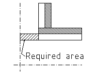
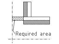
- Details
Company
Engineering procedure for the preparation of process flow diagrams P-T profiles engineering flow diagrams utility flow diagrams interconnecting flow diagrams process safeguarding flow diagrams revamping flow diagrams and line tables
Table of content
-
Introduction
1.1 Purpose
1.2 Concept
1.3 Use
1.4 Types of Diagrams
1.5 Notes -
Scope
-
General procedure for flow diagram preparation
3.1 Layout and Format
3.2 Symbols and Identification
3.3 Diagram Issues -
The process flow diagram
4.1 General
4.2 Initial Process flow diagram
4.3 Kickoff Meeting
4.4 Process flow diagram drafting
4.5 Reissues of process flow diagrams
4.6 Computer vision diagram systems -
The Pressure (p) – Temperature (T) profile
5.1 General5.2 Purpose
5.3 Reissues of P-T Profile
5.4 Computer Vision Diagram Systems -
The Engineering flow diagrams
6.1 General
6.2 Initial Engineering flow diagram
6.3 Pipelines and pipelines referencing
6.4 Initial flow diagram check
6.5 Diagram review meeting
6.6 Engineering flow diagram drafting6.7 Reissues of Engineering flow diagrams
6.8 Computer vision diagram systems -
The utility flow diagrams
7.1 Purpose
7.2 Preparation
7.3 Layout
7.4 Control systems, valves, etc.7.5 Equipment
7.6 Example diagram
7.7 Example diagram -
The interconnecting flow diagrams
8.1 Purpose8.2 Split of work
8.3 Layout
8.4 Example diagram -
The process safeguarding flow diagrams
9.1 Introduction
9.2 General consideration
9.3 Purpose
9.4 Timing and preparation of process safeguarding flow diagram
9.5 Presentation -
The revamping flow diagram
10.1 General
10.2 Updating and Marking engineering flow diagrams10.3 Example diagram
-
Check list
-
preparation of line tables
12.1 Responsibility
12.2 Format
12.3 Description of Columns
12.4 Procedure
12.5 Computer vision systems
12.6 Sample forms -
List of related Company standards
-
List of standards other than Company
14.1 General
14.2 U.S.A.
14.3 West Germany
14.4 Great Britain
14.5 France
14.6 The Netherlands
14.7 S.I.P.M.14.8 Aramco
-
Typical arrangements of equipment installation
15.1 General
15.2 Vessels and columns
15.3 Shell & Tube heat exchangers
15.4 Aircoolers
15.5 Pumps
15.6 Turbines
15.7 Ejectors
15.8 API
15.9 Control stations15.10 Utility tie-ins into process lines
15.11 Battery limits installations
15.12 Sample stations
15.13 Safety relief valves
15.14 Burner installations15.15 Steam trap assemblies
15.16 Instrument purges
15.17 External seal flush and purge
15.18 Cooling rotating equipment15.19 Flushing oil
15.20 Blowdown systems
15.21 Level instruments and stand pipes
15.22 Instrumentation compressors
15.23 Valve type selection
15.24 General instrument requirements15.25 Utility header valve requirements
1. Introduction
1.1 Purpose
The purpose of this document is to outline the procedures for the preparation of process flow diagrams, pressure-temperature profile diagrams, engineering, utility and interconnecting flow diagrams and special diagrams as revamp flow diagrams and pressure safeguarding flow diagrams.
1.2 Concept
Flow diagrams are highly specialized “language” for information transfer. They represent the engineer's concept of how plant equipment should be interconnected. The diagram is almost physical in a sense, since every piece of equipment, every pipeline, valve and instrument is shown. Diagrams are used to convey information between groups working on the project and translate the plant design into “real” piping and equipment.
1.3 Use
By preparing the diagrams properly, the engineer can convey a great deal of technical information, quickly and accurately, with a limited amount of paper work.
1.4 Types of diagrams
There are 7 types of flow diagrams:
1.4.1 The process flow diagram (PFD)
The PFD is developed by the process engineering department. Final drafting by the flow diagram squad.
On this document are given the main process equipment., fluid flows, main control loops and critical valves. It is a tool for the process engineer(s) to convey information to project and specialist engineers to design the installation in detail (see fig: 6)
1.4.2 The Pressure Temperature Profile Diagram (PTP)
The PTP diagram is a document prepared by the Process Engineering Department with the purpose of providing project, control systems and piping engineers with the correct pressure and temperature correlations between the various piping systems, vessels, exchangers, etc.
The document ensures that proper values are being used for preparation of data sheets, line tables and other documents as, e.g. painting systems, insulation, etc.
For PTP preparation procedures refer to Standard Specification BN-EG-UE-1 (Design guide for Pressure and Temperature profile).
1.4.3 The Engineering Flow Diagram (EFD)
On this document are shown all equipment connecting piping, utility piping, complete with control loops and all other instrumentation, all valves and safety measures. It is the main tool for the project engineer to convey information to the piping design office and control systems engineering group for the detailed piping and control systems design (see fig:13)
1.4.4 The Utilities Flow Diagram (UFD)
This document shows how utilities are generated and distributed from the source or supply point to the various parts of an installation. The diagram shows common control loops, additional equipment that is deemed necessary to supply the utility as required and the safety measures necessary (see fig: 18). The diagram shall be drawn in accordance with the geographical layout of the plant.
The diagrams are generally divided per generation activity, e.g. steam generation, instrument air, cooling water, fuel oil, etc. The utility equipment shall be shown. Packaged units to be shown within heavy dotted line.
1.4.5 The Interconnecting Flow Diagram (IFD)
These diagram are prepared to show the interconnecting lines between various plant units and, e.g. tank farms, etc.
1.4.6 The Process Safeguarding Flow Diagram (PSFD)
This document shows the correlation of safety devices installed but indicated on separate EFD's. It “highlights” the final level of protection provided by the safety systems installed.
This document will be produced on client's request only, e.g. SIPM.
1.4.7 Revamp Flow Diagram (RFD)
“Revamping Flow Diagram” shall be prepared to indicate which equipment, lines, control loops, etc. must be demolished, modified, removed or relocated, etc. in a revamping project. The existing engineering flow diagrams of a plant or unit to be revamped shall be used.
In general two sets of diagrams are to be prepared:
a. An updated existing EFD's version for demolishing purposes RFD's.
b. New “as built” EFD's
For more details refer to chapter 10
1.5 Notes:
1.5.1 It must be noted that particular instructions given by client or licensor with respect to his requirements or special requirements covered by any authority decrees shall be observed.
1.5.2 If any of such rules, decrees or instructions exist, these must be mentioned in the “Project Specification”.
1.5.3 When these instructions have not been incorporated, the documents produced will be unacceptable to the client or licensor and/or authorities.
1.5.4 Where in the following text of this Engineering Procedures has been referred to other Company procedures or standards, this is only true where the Company standards are not conflicting with those mentioned under par 1.5.1.
1.5.5 To obtain maximum uniformity with regard to line thickness, lettering, symbols, etc. the drafting on vellums shall be executed by the Flow Diagram Squad.
1.5.6 There is still another flow diagram, prepared by the control systems engineering group, exclusively for use by process and control systems engineers. This flow diagram is principally a PFD on which the control system engineer indicates specific instrument physical data: the document is called: “Instrument Data Flow Sheet”. It is not further mentioned in this “Engineering Procedures”.
1.5.7 The examples presented in this Engineering Procedure are taken from actual jobs and include general Client's requirement. Therefore, the symbols used will not always be identical to the symbols shown on the legend sheet fig:22
1.5.8 On an EFD, a package unit, e.g. compressor, can be indicated with a heavy drawn block with reference to one or more vendor flow diagram (process, lube oil, seal oil, water cooling, etc.) which can be adopted.
2. Scope
2.1 This Engineering Procedure shall be used as a standard for the preparation of precess and engineering flow diagrams as outlined in para 1.4 of the introduction.
2.2 It shall also be used to edit systematically the text for the project specification on the subject of flow diagram preparation.
2.3 The purpose of this Engineering Procedure is to provide the engineers with all necessary information to generate the various diagrams needed with the greatest consistency and efficiency possible.
3. General Procedure for flow Diagram Preparation
3.1 Layout and Format
3.1.1 Vellums
All formal diagrams shall be drawn on standard A-1 size vellums (vellum size 594x841mm, including 10mm edge). In those cases where the project specifications ask for drafting on client's standard forms, the size may be different from the A-1 size.
3.1.2 Title block
The PFD, EFD and other diagrams shall bear in the right hand bottom corner of the diagram the standard Company title block. In cases where project specifications ask for specific use of client's vellums with client's title block, a standard Company drawing number sticker shall be added to the drawing for use of Company drawing record (see figure 1a).

Fig. 1a
In cases where client forbids the use of Company drawing number sticker, the Company drawing number shall be outside the drawing boundary line (see fig:1b).
The title block shall be completed with information as unit number unit name, unit section, drawing number, and all other information that is necessary to give all drawing-related information.
3.2 Symbols and Identification
3.2.1 For each project the engineering and utility flow diagrams will use the Company standards, if not overruled by client's licensor's or authority's requirements. These technical documents are:
BN-DS-C1 General information and Explanation of the Company symbols
BN-ES-C1 Standard symbols for Process and Engineering Flow Diagrams
BN-ES-K1 Standard for Identification of Instruments.
3.2.2 All symbols, instrument identifications and abbreviations used must be conform to those shown in above given standards, unless otherwise noted in the project specification.
In other cases a new legend sheet is to be prepared, which includes the required symbols and abbreviations. Project shall decide, in consultation with client or licensor, which system has to be used.
3.2.3 All equipment shown on the process and engineering flow diagram shall be identified with both name and number as listed on the equipment list.
Placement of titles shall be as follows:
a) Towers, tanks, tubulars, general equipment and other items on or above the upper base line shall be identified with titles placed across the top of the diagram. In some cases a space shall be provided to indicate design and/or operating conditions.
b) Pumps, compressors, etc. on the lower base line. Space shall also be provided to give design/operating conditions, if required.
3.2.4 To save drafting time, the flow diagram squad may make use of preprinted self-adhesive stickers to be stuck to the front or the back of the flow diagrams. These stickers can be adapted to any project an requirement.
3.2.5 Sticker samples
3.3 Diagram Issues
3.3.1 Issue numbering
It is of utmost importance that flow diagrams are kept up to date continuously and are regularly to keep all disciplines informed of the change during the engineering stage.
A release for design issue of flow diagrams shall be made directly after incorporation of Client's comments. Any further change after this issue mad by the Client shall be a subject for a change order.
The reissues shall be distributed in accordance with the job document distribution schedule.
All issues shall be numbered, dated and provided with a short description of the reason for reissue in accordance with QA procedure 006.
Typical example
The issue number shall be in accordance with the required numbering system as given in the job project procedure.
3.3.2 Revision list
All issues distributed after the “preliminary piping materials B.T.O.” shall be accompanied by a “revision list” on standard form BN-UD-101 “List of Revisions”.
This list of revisions (change) shall be issued as an addendum to the revised flow dagram. Each new diagram issue shall be accompanied by such a list of revisions.
3.3.3 Internal Issues
In some cases it may be required to distribute a diagram exclusively for the use within the BBV organization only.
It shall be clear that the number of such “Internal Issues” shall be kept to an absolute minimum. It is even better to have none at all.
In the case however, that an internal issue is necessary, the numbering procedure is as follows:
A circle of 16 mm diameter shall be drawn at the left hand side of the diagram title block and on the backside of the vellum. The circle shall be divided in two parts by a horizontal line.
An index capital A, B,etc. shall be pencilled in the top half of the circle and the issue date in the bottom half. Both capital and date on the front side of the vellum. The first internal issue shall be numbered. A. At the next internal issue the A and date are removed and a B together with the new issue date shall be written in the reserved places.
To keep properly track of these internal issues, the Project Engineer shall keep a record of the internal issues. This record is a very important document and can be a key document with regard to, e.g. material takeoffs.
3.3.4 The revisions shall be indicated by a “cloud” around the change and with the corresponding issue number within that cloud. The clouds shall be drawn with an orange colored pencil, e.g. color code 415, and on the BACK of the vellum. The clouds of previous issues shall be erased before new revision clouds are drawn on the vellum.
Note:
For changes/revisions on prints a standard BBV practice is to use the following color codes:
a. Equipment, lines, instruments, etc. removed from the drawing indicated with “red”, color code 426
b. Equipment lines, etc to be incorporated on the drawing indicated with “blue”, color code 443
c. Equipment lines, etc which are correct may be checked off with “yellow”, color code 407.
d. Remarks and additional notes which are not to be drawn on the vellum, “green”, color code 463.
Above color codes refer to the code numbers used by pencil manufacturer Faber-Castell, Gold Faber pencils. Other manufacturers have not necessarily the same code number system.
Instead of a red color for removing equipment, lines, etc a flesh-colored pencil may be used, which permits to draw new equipment and lines over the removed equipment. Use for this purpose pencil Faber-Castell Polychromos, code number 131.
Engineers are instructed to follow above system very consistently.
3.3.5 All changes on the diagrams shall be recorded on a “project Master” print of the last issue and kept at hand by the project engineer. All changes and/or additions made by others shall be passed through the project engineering department. It is the project engineer's responsibility to see that the diagrams are reissued every one, or at the most, every 2 months to keep all disciplines informed about latest revisions and changes.
3.3.6 All superseded “Project Masters” should be kept in the project file to provide a record of events.
3.4 Coordination
3.4.1 Copies of all correspondence, all specifications, all equipment vendor drawings and other pertinent job documents should be sent to the project engineer so that he may keep abreast of any and all changes which would affect the diagram. The project engineer shall forward all the relevant information to the different disciplines.
3.4.2 Any department, when making revisions or additions, which will affect a diagram, is required to notify the project engineer immediately, preferably in writing or to send hem his “master”. The project engineer will pass this information to the process engineer involved and update his master diagram accordingly for inclusion in the next diagram issue.
3.4.3 Revisions to precess flow diagrams must be brought to the attention of the project engineer. In this manner the project engineer will keep abreast of all process changes and will be able immediately to incorporate the changes into the engineering flow diagrams. After this updating by project, the process engineer will sent his “Master Copy” directly to the flow diagram squad.
It is necessarily for the process engineer to discuss contemplated changes with the project manger/engineer before changing the process flow diagram. The effect on fabrication and deliveries of equipment and/or materials, the client's or licensor's desires and construction schedule should be carefully considered and increasingly so as the job progresses.
4. The Process Flow Diagram (PFD)
4.1 General
After a project has been awarded the Process Department shall provide all special information required to commence engineering.
Process shall prepare a hand-sketched draft Process Flow Diagram which can be used for informing the various disciplines about the work to be performed. This normally is done at a formal kickoff meeting.
4.2 Initial Process Flow Diagram
The Process Department will prepare a had-sketched initial process flow diagram on preparinted standard vellums provided especially for this purpose (Form number E-B-UD15) (see example fig:5.)
The use of this sketch is two-fold. The sketch shall be used as a visual aid during the kickoff meeting and is the basis for the flow diagram squad to start drawing the process flow diagram proper. See example fig:6
4.3 Kick-off Meeting
4.3.1 Before engineering is started, a conference shall be called by the project manager to discuss the process and mechanical aspects of the job. This meeting should be attended by the job process engineer(s), project engineer(s), manager design engineering operations, design engineering supervisor, lead control systems engineer, lead piping engineer and other lead specialist engineers, as required.
4.3.2 A detailed explanation of the process shall be given by the process engineer. He outlines special considerations required for the location of related equipment, both in plan and elevation and calls attention to pipelines which must be arranged for gravity flow, tow-phase flow, self draining, etc.
At this meeting, the general philosophy of the control systems shall be discussed, particularly what types of instruments are to be local or remote, which indicators will be trend-recorded, the number of special analytic instruments, data loggers or other unusual requirements.
The process engineer should emphasize anticipated corrosion or erosion problems, explain the basis for the selection of materials of construction and review any special problems which must be considered in the mechanical design of the plant.
It is essential that the project engineer be given a thorough understanding of all process and operating problems at the project outset. In this way the information given on the initial diagram Layout will be as complete and accurate as possible.
4.4. Process Flow Diagram Drafting
4.4.1 Before the job starts, the project manager, in consultation with client or licensor, has to decide which system has to be followed, i.e. all process data, material balance, etc. should be shown on the process flow diagram proper, or that a separate set of material balance sheet will be prepared.
This information is necessary for the equipment layout on the diagram.
4.4.1 The flow diagram squad starts with the hand-sketched process flow diagram, from which the process engineer has given the explanations described in para 4.3.1, to make the process flow diagram on the proper format and with the standard symbols given in BN-ES-CI-1 and BN-ES-KI-1, or, if necessary, translate the Company symbols into symbols required by the client. This flow diagram will only be issued to the process engineer in charge to give on a print more information, such as heat duties, capacities, pressures, temperatures, equipment sizes on towers and drums, and capacities and P's for pumps.
4.4.3 It is essential to show a process flow diagram as simple as possible as far as mechanical details are concerned. It has to be avoided to show too many valves, etc. , and only the main instruments have to be given when laying out a process flow diagram. Ample space shall be provided for process data such as capacities, pressures and temperatures and instrument data on IDF sheet (see 1.5.6).
4.4.4 When all this information is shown on the process flow diagram, this will be officially issued by the project manager.
4.5 Reissues of Process Flow Diagrams
During the progress of the project the process flow diagram shall be reissued when necessary with the purpose of keeping all disciplines properly informed about the changes and corrections forthcoming during the engineering stage. For issue frequency and numbering see para 3.3 Issues are distributed in accordance with the job distribution schedule by the Project Department.
4.6 Computer Vision Diagram System
At the time this guide was updated and reissued plans to incorporate the means of producing flow diagrams by a computerized system were approved. In due time the guide will be updated to include the necessary information for generating computerized process flow diagrams and pressure-temperature profile diagrams. For example of such diagram see fig: 7
5. The Pressure-Temperature Profile Diagram (PTP)
5.1 General
The PT profile prepared by the Process Department is basically the process flow diagram on which for all critical flows through control valves and lines the following data may be given as deemed necessary for the project.
- Normal operating pressure
- Maximum operating pressure
- Normal operating temperature
- Maximum operating temperature
- Molecular weight
- Design pressure
- Design temperature
- Density
- Viscosity
- Normal flow
- Maximum flow
- Maximum temperature thermal stress
- Maximum shutoff pressure for pumps
- Set pressure of relief valves/break plates
- Differential pressure of pumps.
5.2 Purpose
The PT profile shall be used by all disciplines in order that the use the proper values of pressures and temperatures applicable to their specific requirements, e.g. pipe stress engineers, control system engineers, etc.
5.3 Reissues of PT Profile
The process engineer shall keep the data on the PT profile up to data and have the diagram reissued when necessary by the project manager.
The data on the PT profile must be “Certified Final” as early as possible, in order to minimize extra work because of process data changes.
5.5 Computer Vision Diagram Systems
When the computer vision diagram becomes operational (refer to para 4.6) the PT profile shall be made using the available info to produce a process flow diagram and the required PT profile data (see example fig: 7)
6. The Engineering Flow Diagrams (EFD)
6.1 General
A simplified block diagram showing the key elements of a systematic approach to flow diagram preparation is given in figure 8.
6.2. Initial Engineering Flow Diagram
6.2.1 The project engineer shall make the initial diagram layout for the engineering flow diagrams based on the process flow diagram. He should make the layout free hand and to full scale on the standard flow diagram vellum E-B-UD15 (see fig 5). The free hand edition should be initialed and dated by the project engineer and black and white prints distributed to the process and control systems engineers. See attached example, figure 9.
6.2.2 EFD General Layout
The EFD's shall be laid out with three horizontal zones across the sheet. Across the lower middle portion of the drawing is the “pipe alley” containing lines which enter and leave the sheet to other EFD's in the same unit plus lines running between pumps and other pieces of equipement on the drawing. Pumps and pump stations shall be located along a line below the “pipe alley”. All pump valving shall be lined up. All other equipment shall be located above a base line above the “pipe alley”. The general flow scheme shall be read from left to right. Unnecessary line crossing should be avoided. All line numbers and flow arrow shall line up as far as practical.
General notes for each unit are to be indicated on only the first sheet of the unit. The area above the title block on this sheet shall be completely left open for notes. Diagrams showing special equipment such as burner and compressor controls, etc shall have the related special notes on the same diagram.
6.2.3 Equipment
To be shown on the EFD:
a) Each piece of equipment including spares on the EFD of that particular unit. When an item is to be physically located inside the area of another unit it shall be so noted, exception may be made for situations where a large number of identical trains exist.
b) Pump item numbers and titles below the pumps “base line”. Indicate pump train designation only under each pump base (e.g. A.B.C.). When spares are required, the last pump of a train shall always be considered spare.
c) The other equipment item numbers and titles across the top of the flow scheme with the item number duplicated on or near the piece of equipment at its location on the diagram.
d) The equipment outline as simply as practical, but including all essentials and outlines, e.g. body flanges, domes, etc.
e) All connections and instruments on equipment. All connections whose purpose is not readily evident shall have the purpose indicated (examples: spare inlet, UC etc.), and the piping class to be used for the trim of the equipment.
f) Essential internals shall be shown in phantom so as to clarify the laction of connections relative to the internals. Vortex breakers are also to be indicated.
h) Motors on pumps only when connected to an interlock.
h) The support for columns and vessels supported by legs or a skirt.
j) A gap in the vessel support where a bottom outlet line crosses a vessel support.
k) Exchangers in side profile, with indication of expansion joints, tube side distribution baffles, etc., if any. Each shell te be shown and in relative position if stacked.
l) Bundles and fans on airfin coolers shall be shown simplified, but details on louvres, winterizing, running lights, temperature regulations and piping connections are to be shown if necessary on separate sketches.
m) A list next to the left hand side of the title block indicating the item numbers of equipment contained on the particular flow diagram.
n) Vendor-supplied packages only as a dashed/dot “box” with an outline of the main component(s) inside. At a proper time the reference drawing numbers are to be added.
o) The relative size of equipment – although no to scale.
p) The relative elevation of equipment – although not to scale.
q) Critical elevation notes as required.
r) Nozzle size when line size is different, reducers where applicable.
s) Existing equipment, when required, shall be shown with a dash-dot line, and marked “EXISTING”.
t) Manholes on columns/vessels.
u) Flushing/seal oil systems.
v) Start-up/shutdown lines.
6.3 Pipelines and pipeline referencing
6.3.1 All pipeline branching should be shown in proper sequence.
6.3.2 When lines cross one another, preference should be given to horizontal line, i.e. all horizontal lines should be continuous and vertical lines broken to cross them.
6.3.3 The procedure for cross referencing of pipelines going from sheet to sheet is as follows:
a) All main and process lines should enter and leave the diagram right or left (see figure 10) . An exception has to be made for lines coming or going to another unit. Those lines are coming in or leaving the sheet in a block (2x5cm) below the lowest pump base line (see figure 11).
b) Lines should enter and leave a diagram in a manner consistent with the actual process, where possible.
c) Whenever possible a line should match its continuation on a following diagram where possible. Line crossings as shown in fig 10 shall be kept to a minimum.
d) On each side of the flow diagram a dashed line shall be drawn to show from which diagram a line comes or to which one it goes. References and line numbers should also be added to lines where they enter or leave the sheet (see fig. 10).
e) A line shall not run across a sheet unless it ties into another line or piece of equipment on that sheet. It is permitted to skip one or more intervening sheets when running a line from one sheer to another.
f) All utility lines should be shown on the engineering flow diagram terminating in a diamond which shows the abbreviation as indicated on the legend sheet (see fig.12). The utility lines shown on EFD's shall only show instrument, valves, etc. directly related to the connected equipment (see fit. 13). The utility header valves and instruments will be shown on the utility flow diagram (see fig. 16). Example of legend, see fig:22.
g) The size of control valves shall be noted, e.g. 2”. If equipped with reduced size trim, body and trim size shall be noted, e.g. 2”x1,5”.
h) The size of relief valve inlet and outlet connections shall be noted, e.g. 3”x4” and must be shown below the relief valve number, including the set pressure, e.g:
j) The size of any valve not line size shall be noted. Reducers etc. shall be shown.
k) Any valve specified by the project engineer which must be other than a standard type identifiable by symbols and piping class specification, shall be identified by an “MM” number assigned by the material control section.
l) For line numbering refer to section 12.
m) For some instruments, like flow or temperature instruments, a pipeline shall, over a short distance, be enlarged or reduced as indicated by the instrument engineer.
m) For some instruments, like flow or temperature instruments, a pipeline shall, over a short distance, be enlarged or reduced as indicated by the instrument engineer.
n) All lines and connections shall show their respective size. In case the actual size is not yet known, the indicated size shall bear a note 'assumed'.
6.4 Initial Flow Diagram Check
The process and control systems engineer should each review this initial layout and should note on their copies all corrections and additional information available to them at this phase of development. Each reviewing engineer should return his copy to the project engineer. The project engineer has to take over all comments and additional information on the project master copy and return the process and instrument copies to the engineers concerned, as the keep a record for their own references.
6.5 Diagram Review Meeting
6.5.1 After the process and control system engineer's additions and/or corrections have been incorporated on the project master copy, the project engineer should hold a conference to discuss these additions and corrections.
6.5.2 It is important that the diagram be as complete as possible at this stage, however, the progress should not be retarded by incomplete details which can be added later.
6.6 Engineering Flow Diagram Drafting
The up to date project master copy is then sent to the flow diagram squad of the design engineering group. The vellum(s) will be updated in accordance with the marked up master copy and prepared for Issue I (or O or A; according to the project specification) “For Client's Comments” or “For Client's Approval”. A check print of this diagram will be sent to the project engineer for a last review. When comments of this review have been incorporated, the vellum will be signed and dated in accordance with procedure QA-006 and released for issue.
6.7 Reissues of Engineering Flow Diagrams
During the progress of the project, the EFD's shall be reissued when necessary with the purpose of keeping all disciplines properly informed about the changes and corrections forthcoming during the engineering stage. For issue frequency and numbering , refer tot para 3.3.
6.8 Computer Vision Engineering Flow Diagram System
At the time this guide was updated and reissued, plans to incorporate the means of producing EFD's by a computerized system were approved. In due time the guide will be updated to include the necessary information for generating EFD's by computer. For example of such diagrams see fig. 14
and 15.
7. The Utility Flow Diagrams (UFD)
7.1 Purpose
The primary purpose of the utility flow diagrams is to facilitate correct utility line sizing and to give this information to the piping designer as soon as possible.
7.2 Preparation
The utility flow diagram shall be prepared by the project engineer. A careful check must be made with the piping squad leader to ensure that the utility flow diagram is consistent with the piping design.
7.7 Layout
Utility flow diagrams are laid out suing format E-BN-UD2. The pipe rack(s) on the vellum should be shown as a “landmark” which must be the same on all drawings with the various groups of utilities. This vellum does not need to be on scale but it must present the various areas items in their relative geographical locations.
One sheet should be used for each utility system although several services could be shown on the same sheet if there are few users for each utility. Avoid overcrowding these diagrams, but be sure that every utility connection and branch is shown.
Additional equipment, if being serviced by any particular utility, should be added to the sheet. Remember that at a later date a number of service stations (SS …..) have to be added at the following utility flow diagrams:
Water System Diagram (see fig. 16&17)
- Steam System Diagram
- Plant Air System Diagram.
Note:
Sometimes nitrogen or inert gas Lines are also incorporated in utility stations for purging purposes (reactors or compressors).
7.4 Control Systems, Valves, etc.
Only piping riot already shown on the engineering flow diagram should be shown on the utility flow diagram. Instruments and. valves should not be shown on a flow diagram, unless they apply directly to the utility and are independent of the process (see also 6.3.3, para f).
As an example of this type of exception might be a pressure-reducing controller and its valves from a high pressure to a low pressure steam header. Care shall be taken that valves are not shown twice, e.g. on the EFD and on the UFD.
7.5 Equipment
Process equipment shown on the utility flow diagram should be represented by squares of 2 x 2 cm with the information given as in figure 17. More detail than this is not wanted nor required. The only equipment to be shown in detail on a utility flow diagram is special utility equipment such as a steam boiler, a cooling tower, instrument air drier, etc. Packaged units as a part of a complete offsite utility system, may require a separate utility engineering flow diagram.
7. Figure 16 is an illustration of a utility flow diagram (draft).
7.7 Figure 18 is an illustration of a utility flow diagram when drafted by the flow diagram’ squad.
7.8 A separate UPD shall be prepared showing detailed sketches for miscellaneous pump piping with all valves, instruments and safeguarding requirements.
7.9 All Lines and branches shall be sized. U the final size cannot yet be determined, an ‘assumed’ size shall be shown and marked as such.

8. The Interconnecting Flow Diagram (IFD)
8.1 Purpose
The purpose of the interconnecting flow diagram is to show how and where various units, that make up the process plant, are connected with each other. This includes also possible tank farms, loading areas, other process plants, etc.
The lines that connect the units are normally located on pipe bridges and in trenches. These pipe bridges and trenches are to be used on the diagram(s) as landmarks and to obtain, as in the case for utility flow diagrams, a geographical layout. The diagrams shall indicate where at battery limits valve manifolds are located for distribution, bypass or shutoff purposes.
Also instruments physically located on pipe bridges, in trenches, and at valve manifolds, for as far as not shown elsewhere on EFD’s, shall be indicated.
8.2 Split of Work
Where a project is split in an “onsites” and an “offsites” part by others, the diagrams shall also be used to indicate clearly the location of the split in scope of work.
Standard Company indications on the diagrams under notes:
![]()
8.3 Layout
As already mentioned in para 8.1, the layout of the diagram(s) shall follow the geographical layout of the process plant.
The individual plant units for which a set of ETD’s have been prepared, shall be represented by a block on the drawing. Within this block the name and reference number of the unit shall be given. Each connecting line to or from this plant unit, either coming from other plant units, tank farm, other process plants, etc. shall be clearly identified, giving following data as minimum requirement:
a) Fluid name.
b) The pipeline number complete with. index capital, size and line class.
c) A reference to the EFD, UFD, etc. on which the continuation of the pipeline can be found.
All lines shown on the diagram shall be numbered in accordance with Company standards (see section 12) or in accordance with instruct given in the project specification.
8.4 Fig. 19 is an example of an interconnecting flow diagram.
9. The Process Safeguarding Flow Diagram (PSFD)
9.1 Introduction
Process Safeguarding Flow Diagrams shall only be prepared when asked for in the job project specification.
Since the Process Safeguarding Flow Diagrams are presently required by only one client, this Engineering Procedure does not include detailed instructions for the preparation of these diagrams. Refer to client’s instructions when these diagrams are required.
9.2 General Considerations
The PSTD of a process is intended to assist concerned parties in understanding the influence of safeguarding: protective instrumentation systems on equipment operation and process variables
When PSFD’ s are prepared, they shall be included in the design book and in the operating manuals of new units. The diagrams are to be included for instruction purposes in the chapter on “Safeguarding”.
9.3 Purpose
The PSFD is NOT a substitute for an Engineering Flow Diagram (EFD) of a particular unit. Often there are quite a number of EFD's per processing complex and the influence of operational upsets between one unit and another are not always readily recognized.
The PSPD should therefore clearly show the interrelation between various units and with processing plants outside battery limit including utilities, relief and blowdown systems, etc. It should high1ight the effect of one process on another from an equipment protection point of view, as far as potential loss of containment is concerned.
9.4 Timing and Pre of Process Safeguarding Flow Diagram
The PSFD shall be prepared from the Engineering Flow Diagram by the project engineer.
Modifications to the design automatically mean reassessment of the final level of protection of plant equipment. It is for this reason that alter modifications it is vitally important that also the PSFD is kept up to date..
The PSPD is a tool for checking that the unit is adequately protected. In order to save duplication of work the PSFD should be prepared after the EFD’s have been APPROVED, i.e. when the comments and modifications in the design have been incorporated. However, the PSFD should be correct at the time the EPD is issued as FINAL.
9.5 Presentation
If possible the PSFD of a unit including its relevant tie-ins with other units, should be confined to one sheet per unit. Tie-ins with other units nay figure twice, i.e. on the PSFD of each unit.
The same symbols should be used as for a Process Flow Diagram (PTD).
Equipment (vessels, pumps, etc.) and instruments shown should carry their tag-number.
A PSFD of furnaces need not be prepared. Furnace firing control and safeguarding should be on separate EFD which are adequate in themselves. Only if fuel Tight Shut Off valves are shut by process signals the TSO valve and the fuel Line may be shown.
10. Revamping Flow Diagrams (RFD)
10.1. General
Before updating of EFD’s for a revamp project can be started it must be made absolutely certain that diagrams are fully in accordance with actual installed equipment and relevant piping systems.
It is therefore necessary that a piping system squad visits the plant area for a site verification. During such a visit existing EFD’s are updated for the involved areas.
10.2 Updating and Marking EFD’s
10.2.2. After the site verification has been made the EFD vellums are corrected and handed to project.
10.2.2 Project is responsible for the preparation of a set of RfD’ s indicating which pipelines shall be removed, equipment to be removed, reinstalled, modified, etc.
Prints of the marked up vellums are distributed to inform all disciplines what has to be modified.
A set of piping arrangement drawings can with this information be modified to demolishing drawings.
2.0.3 Marking-up Cede
To obtain uniformity in the marking-up of RFD’s the following has been standard practice with Company.
10.3.1 Pipelines that shall be removed from the existing installation will be crossed out on the RFD as follows:
10.3.2 Cutting point and tie-in locations are to be indicated by an ellipse with the corresponding cutting or tie-in number written in it.
New equipment shall be marked “X”
Modified equipment shall be marked “Y”
Modified and relocated equipment shall be marked “Z”
Relocated equipment shall be marked “V”
10.3.3 The marked up diagrams shall be accompanied by a “mark-up list on which all cutting/tie-in points as well as all equipment shall be noted and numbered.
10.3.4 It shall be noted that the marked up RFD’s are to be used for preparation of various basic documents.
Depending on the complexity of the revamp, new EFD’s may be required.
New PFD’s and/or EFD’s are to be prepared in accordance with guidelines given in chapters 4 and 6.
Care shall. be taken that when new PFD s and EFD’s are to be prepared, the old PFD’ s and EFD’s shall be reissued in full d including that of client, as Deleted.
Note on the diagram: This diagram has been replaced by drawing no.
Marked up RFD’s for demolishing purposes shall be marked
For demolishing only
10.3.5 No information on demolishing drawings shall be removed by erasing Only crossing out as described in para 10.3.1 is permitted.
10.4 Example of Typical Demolishing Diagram Fig: 20.
10.5 Complicated Revamps
For highly complicated revamps, the foregoing procedure may not lead to satisfactory results as the marked-up RFD’s will become unreadable.
In such cases, the following procedure may be considered:
- New EFD’s to be prepared from the PFD’s in accordance chapter 6.
These EFD’S should reflect the situation after the revamp as if a new plant is being built.
- These EFD’s will be carefully compared to the EFD’s that reflect the existing situation and marked-up to show which lines, nozzles, instruments etc. can be re-used and which will have to be new.
New equipment and lines will be shown in heavy contours brought on the vellum at the backside to facilitate removal after the plant has been started-up.
- Demolishing RFD’s will be prepared on a reproducible of the existing EFD’s by comparing New EFD’s to Existing EFD’s. (refer para 10.3.1.)
An example of such new EFD’s is given in fig: 21.
- Indicate size of relief valves (control systems engineer).
- Show all valving (excluding sample and. bleeder valves, of instruments).
- Always date any flow diagram when printing, it for issue in accordance with para 3 3.
- Check which lines require steam tracing and select type of steam tracing
- Give equipment numbers shown on diagram in alphabetical order at the lefthand side of drawing title block.
- Ensure that all lines, branches and equipment connections are sized and shown
11. Check List
- Make all flow diagrams on standard flow diagram vellums (E-BN—U15) (fig. 5).
- Provide ample room around all equipment for instrument details, auxiliary piping.
- Use the standard legend sheet 00107A as cover sheet for all flow diagrams on a job (SN-ES-C1-1, sheet 28-30).
- Use symbols in accordance with instructions in project specification.
- Show equipment in outline form only except internals essential to external piping.
- Show all connections on equipment with size, including spare and blank connections, irrespective of line size.
- Indicate nozzles on equipment as per vessel sketches, e.g. N1; N2; Kl; K2, etc.
- Check the diagram versus the Company vessel drawing to be sure that all connections are shown in proper relative location.
- Show important equipment internals in phantom.
- Check correct connections on exchangers versus Company specification and drawing.
- Give sizes of valves which are not line size, show reducers where applicable.
- Show flows entering and leaving equipment as the process engineer intends.
- Put line number and title on each line as it enters or leaves a diagram.
- Number and size all lines on the diagrams as soon as possible. (All process line sizing by process engineering; all utility, tankfarm, etc. line sizing by project engineering, in consultation with process where necessary.) An assumption is to be made for lines not yet firm.
- Prepare the line table as the diagrams are being prepared and issue simultaneously.
- Show all instrumentation on the engineering flow diagram that is shown on the process flow diagram.
- Indicate sizes of all control valves and the size of the bypass, where required.
12. Preparation of line tables
12.1. Responsibility
The project engineer assigned to make the EFD’s shall also prepare the line tables required for these diagrams. He shall obtain all needed information from, e.g. the engineer who prepares the diagrams for utilities, etc. The project engineer is responsible for the completion of all co1mns on the line tables with the exception of line sizes for process and flare lines (see pars 12.3.5). Note that some clients have their own line tables which differ from Company standards.
The operating and maximum service conditions, requirement of tracing and insulation temperature are filled in by the project engineer and checked by the process engineer.
12.2 Form
The Company standard form BN-UE-l07 will be used for the line table.
Fig: 24
Note:
In the Company organization exists also a standard form BN-UE-108A which is a special Line table used for Dutch projects subject to Stoomwezen” (Dutch Boiler and Pressure Vessels Authorities) approval. This form will not be discussed in this paper. Refer to example Line table fig. 26.
12.3 Description of Columns
12.3.1 Form Head
In the “Form Head” the Company project number, title, unit number for Company and client, drawing and sheet numbers, shall be properly filled out on each sheet.
Issue and date to be filled in every time the line table is issued (refer to para 3.3.1 for descriptions).
The issue of the line table shall be simultaneous with the issue of EFD’s. and UFD’s.
12.3.2 Fluid – column A
The name of the fluid being handled should correspond to one of the fluids Listed in the job piping specification BN-SP-C2 so that a suitable class specification can be selected. The same name should be used consistently throughout all the lines in the same service. Names should be abbreviated t letters whenever possible, e.g. CW, STM. These abbreviations must e the same as used on the P&I Legend Sheet (see fig; 22).
12.3.From and To columns B and C
Origin and destination of a line should be simple but clear, e.g.
|
From |
To |
|
Line P10112 |
PP1001 |
|
AS1001 |
Line P10122 |
|
TT1003 |
PP1002 |
|
East B.L. |
AS1001 |
12.3.4 Line number – column D
The project engineer shall assign basic numbers according to the following procedure.
A Line number shall consist of a letter followed by a five-digit number. The first two digits shall be the unit number followed by a sequence number.
Process unit lines shall be assigned in sequence number blocks wherever possible, and referenced as a block on the Line table cover sheet. For example, reactor area lines might be numbered. . 101 to 200.
Process line numbers shall, have the letter prefix “P”.
Utility Line numbers and other non-process lines shall have a letter prefix according to the following code, with further sequence number block assignments preferable for different levels of steam, etc.
A001 to A999 – Air
C001 to C999 – Condensate
D001 to D999 – Drains, Blowdown, etc.
F001 to F999 – Fuel Oil, Gas
G001 to G999 – Inert Gas or Nitrogen
K001 to K999 – Chemicals
R001 to R999 – Refrigerant
S001 to S999 – Steam (all levels)
V001 to V999 – Vent and Relief Headers
W001 to W999 – Waters (cooling, tempered, potable, boiler, feed, etc.
Each Line shall in principle have only one origin and one destination. A pump and spare require a total of four Line numbers, one to each suction, and one from each discharge, however, one should take into account that, where possible, a minimum of isometrics drawings by APD system shall be obtained. By giving line numbers, the project engineer shall take into account which system for isometric drawing production is applicable.
It is riot necessary to have a separate number for control valve bypasses, or when a line changes class, per the Latest APD system.
Note:
On some projects it is permitted to have after every 10 or 15 line numbers some spare line numbers reserved. This to obtain maximum continuity in the line numbering when during the engineering phase of the project lines have to be added..
12.3.5 Line size column E
Sizes for process and flare system Lines are determined by the responsible process engineer. Sizes for utility and other non-process lines are determined by the responsible project engineer who in some cases may consult the process engineer and request to review or even assume complete responsibility for some non-process lines..
Whenever such a split of work is desired it shall always be at the discretion of the project manager.
Line sizing shall be done in accordance with the criteria given in the Process Standard Data Book.
The process and project engineers shall carefully check, their calculations after the actual piping configuration has been determined.
12.3.6 Material class - column F
Classes shall be assigned for each lines depending on the fluid being carried, and its required design pressure and temperature. The selection of a suitable piping material for corrosive fluids is made by the piping engineer after consultation with project and/or process engineer. Consideration of conditions other than maximum service as enumerated in 12.3.10 below must be undertaken to properly classify lines.
12.3.7 Schedule number - column G
The wall thickness is the thickness indicated in the piping specifications, as a pipe schedule. For “standard pipe classes” it is not necessary to fill in this column. However, the wall thickness should be included for all special services such as:
Boiler code piping
Special high temperature or high pressure piping
Services requiring unusual corrosion allowances.
12.3.8 Operating temperature - column H
This is the temperature of the fluid during normal continuous operation. This temperature will be the basis for setting the insulation thickness, unless a special note is included in the remarks column, by the process engineer or project engineer.
12.3.9 Operating pressure – column H
This is the pressure occurring simultaneously with the. stated operating temperature.
12.3.10 Maximum service temperature and pressure - column J
These are the most severe temperature and pressure conditions occurring simultaneously during continuous operation of the plant. If there are more severe conditions not occurring simultaneously or not associated with plant operation, they should be stated separately as different design conditions (see 12.3.10 (a) below)
The maximum service temperature and pressure are used in the selection of the piping class. In all situations where the conditions are close to the upper limits of a class or force the use of a higher class than that required by the operating conditions, the conditions and class selection should be reviewed by the process engineer and forwarded to the piping engineer.
The maximum service temperature is and pressure are used in the design for the pipe expansion and for painting, unless a higher, non-simultaneous temperature controls.. In this case, the higher temperature should be stated separately per paragraph. above. Special attention shall be given to flare lines, which may become very hot over short periods.
(a) Other maximum conditions
The conditions affecting design of lines other than normal operating temperature and pressure must be recorded, if they affect design or insulating of lines in the remarks columns or in an addendum to the line table. This applies to emergency conditions, start-up, shut-down, steam-out, preconditioning decoking, reactivation, pump shut off head, thermal expansion of fluids, steam tracing, or evacuating by vacuum, heat conservation dictated by process and oat economics.
The acceptable temperature for steam-out temperature at nearly atmospheric pressure is 120°C. This applies to any supply steam temperature.
When steam tracing is used, a differential temperature of 25°C can be allowed between steam condensate temperature and pipe wall temperature.
(b) Code statement on operating and maximum service conditions
(Excerpt from American National Standard Code for Pressure Piping - Petroleum Refinery Piping ANSI B31 .3.)
302.2. Normal Operating Conditions
For normal operation, the design pressure and. temperature shall not be greater than the pressure-temperature rating of the components. In the absence of such rating, the design pressure shall not result in stress exceeding the allowable stress for the material, at the temperature.
302.2.4 Allowances for Variations from Normal Operating Conditions
Variations in the temperature and pressure, or both, from normal operating conditions are characteristics of certain services. If these variations are infrequent and of short duration, the pressure-temperature ratings (or the allowable stresses) of the piping components may be adjusted as follows:
(a) If the increased operating condition will riot exceed 10 hours at any one time or 100 hours per year, it is permissible to increase the pressure rating (or the allowable stress) at the temperature existing during the increased operating conditions, by a maximum of 33%.
(b) If the increased operating condition will not exceed 50 hours, at any one time or 500 hours per year, it is permissible to increase the pressure rating (or the allowable stress) at the temperature existing during the increased operating condition by a maximum of 20%
Special consideration should be given to the above allowances when setting maximum service conditions.
Cyclic operation
In many chemical processes, lines and equipment are subject to planned cyclic changes in pressure and/or temperature. Frequently these operations are controlled by means of elaborate cycle timers.
The selection of line materials and the design of the whole piping system demands a full and accurate description of the cyclic operation in terms of times, temperatures and pressures of all equipment and piping elements,
To provide this information to all concerned, a full set of explanatory notes and time-sequence diagrams should be incorporated into the line table as an addendum and issued with it. The maximum service conditions will be shown n the addendum rather than in the line table for the lines affected.
12.3.11 Testing – column L
The test pressure shall be calculated according to ANSI B31.3 requirements, except for non-critical, non-hazardous services, where service testing is acceptable. Typical examples of lines that may be accepted with service tests are low pressure, large diameter ducts; low pressure steam, cooling water; condensate; and instrument air. The project engineer shall complete this section, adding the test media and obtaining client approval for service test plans.
12.3.12 Tracing type - column L
The type of tracing or jacketing should be added according to the symbols defined on the P&I Legend Sheet, Drawing No. BN-. . . -00107A (fig: 22). On jobs requiring extensive tracing, additional columns should be added to the applicable line table sheets to indicate Thermon Grade and Steam Pressure.
12.3.13 Insulation and paint code – columns M and N
Insulation thickness and painting code shall be filled in in accordance with applicable job number and R specification.
12.3.14 Flow diagram number - column 0
The flow diagram number on which the corresponding line appears (originates) shall be filled in.
12.3.15 Remarks - column P
Space reserved for additional information
12.4 Procedure
12.4.1 The project engineer prepares the line table in accordance with paragraph 12.3.2, 12.3.3 and 12.3.4 above. He then issues the format to the process engineer.
12.4.2 The process engineer adds the line size and checks the operating temperature, operating pressure, and maximum service temperature and pressure on the Line table prints and returns the forms to project for interim use by project or design.
12.4.3 The Project engineer adds the material class based on the maximum service conditions.
Note:
When high pressure and/or temperature indicate the selection of alloy materials the project engineer is expected to recheck line velocities and maximum operating conditions and governing design conditions with process to assure the most economical line size and class specification. Sometimes a small extra pump head is cheaper t an increase in line size. Sometimes maximum service conditions or governing design conditions are at first set too much above operating conditions resulting in unnecessarily high pipe class specification ratings.
12.4.4 Project completes the table for issue, according to QA-O06.
12.4.5 Revisions are made according to 12.3.1.
12.4.6 For revamp jobs, the project engineer must include all lines affected by the revamp on the LDT.
12.5 Computer Vision System
At the time of reissue of this procedure the plans to incorporate the computer vision system has been approved.
When the system becomes operational then also the line tables are to be produced by using the information stored in the computer memories.
Detailed instructions will be incorporated in this procedure in due time when more information becomes available.
For example of such computer produced line table see fig. 27.
Sample Forms
Figure 23 is a sample line table cover sheet with notes
Figure 24 is a sample line table sheet. Form BN-UE-107A.
Figure 25 is a sample line table sheet. Form BN-UE-107B (for other than ISO units)
Figure 26 is a sample line table sheet. Form BN-UE-108A (for use by Dutch Boiler and Pressure Vessel authorities).
Figure 27 is a sample line table produced by “Computer Vision” method.
List of Related Company Standards
BN- EG –UE-1 Pressure ad Temperature Profile
BN-EG-UE-2 General Rules to Establish Mechanical Design Pressures and Temperatures.
BL-EP-206 Equipment Numbering
BC-EP-210 Preparation of P&I and Utility Diagrams
BL-EP -210A Preparation of Flow Diagrams (PFD, P&I, UDD)
BL-EP-210B Preparation of Flow Diagrams (P&I, PFD, UFD)
BL-EP-210C Preparation of Flow Diagrams (line numbering and tables)
BL-EP-210D Preparation of Flow Diagrams (determination mechanical design conditions)
BA-EP-377 Instrumentation Symbols and Identification
14. LIST OF STANDARDS OTHER THAN COMPANY
14.1 General
This list does not pretend to be complete. It only serves to guide the project engineer through the maze of many documents issued by government authorities and companies.
Before any drafting shall be started it is good practice to check which documents are applicable and that the latest issues of these are at hand.
14.2. U.S.A.
ANSI Z-32.2.3 Graphic. Symbols for Pipe Fittings, Valves and Piping
ANSI Y-32.11 - 1961 Graphic Symbols for Process Flow Diagrams in
ASME K40 Petroleum and Chemical Industries
ISA SS.1. Instrumentation Symbols and Identification.
14.3 West Germany
DIN 19227 Blatt 1- Graphic Symbols and Identifying Letters for Process Measurement and Control Functions.
Part 2 Measurement and Control, Graphical Symbols and Identifying Letters for Process Measurement and Control Functions; Symbols for Instruments.
Part 3 Measurement and Control, Graphical Symbols and Identifying Letter for Process Measurement and Control Functions; Symbols for Basic Functions.
DIN 28004 Part 1 Flow Sheets and Diagrams for Process Plants, Types of Flow Sheets, Informative Content.
Part 2 Flow Sheets and Diagrams for Process Plants, Drawing Instructions.
Part 3 Flow Sheets and Diagrams for Process Plants, Graphic Symbols.
Part 4 Flow Sheets and Diagrams for Process Plants, Assignments of Item Numbers and Piping
14.4 Great Britain
BS 1553 Specification for Graphic Symbols for General Engineering
Part 1 Piping Systems and Plants
BS 1646 Symbolic Representation for Process Measurement Control Functions and Instrumentation
Part 1 Basic Requirements (equal to ISO 3511/1)
BS 5536 Specification for Preparation of Technical Drawings and Diagrams for Microfilming
14.5 France
AFNOR Z-09-0l0 Engineering and Design Documents, General User’s Guide
NF X 02-105 Symbols for Liquid Mechanics
NF E 04-202 Graphic Symbols for Chemical Engineering
Note:
There are a lot more French standards issued. Before starting drafting the diagrams check which standards are applicable.
14.6 The Netherlands
Ontw. 2195 Technical Drawing Symbols for Process and Engineering Flow Diagrams
NEN 3157 Technical Drawing Instrument Symbols. Basic Symbols for the Process Instrumentation
NEN 3347 Technical Drawing Instrument Symbols Advanced Symbols for Process Instrumentation
14.7 S.I.P.M.
DEP 31.10.03.10-Gen. Symbols and Identification System Mechanical
DEP 32.10.03.10-Gen. Symbols and Identification System Instrumentation
14.8 Aramco
AE5-J.4 Identification and Symbols, Section IV, Index A, Drafting Manual
DA-299407 Symbols and Abbreviations
DA-299408 Instrument Symbols
DA-299409 Instrument Identification.
15. TYPICAL ARRANGEMENTS OF EOUIPMENT INSTALLATION
15.1 General
In this addendum a number of typical equipment installations are given which are common in many industrial plants.
It does not pretend to be 100% complete and only serves as a guide to obtain maximum uniformity.
For each project this addendum needs to be updated in accordance with client’s, licensor’s or authority’s requirements.
The updated version of this addendum may be made part of the chapter on flow diagram preparation in the project specification.
It should be noted that some clients use the word ‘Scheme’ instead of ‘Diagram’. The latter being the indication used by Company.
If the word ‘Scheme’ is standard for a particular client, then the text of the addendum must be adapted accordingly before it shall be used in the project specification.
15.2 Typical Installations for Vessels and Columns
Notes:
(1) Indicate all nozzles shown on the equipment data sheet.
(2) Provide spectacle blinds at nozzles
(a) 10 inches and larger
(b) where piping is obviously rigid.
Note:
Add spectacle blinds in other lines which are designed rigid, during detailed engineering phase).
The general philosophy is to blind at equipment nozzles for maintenance operations. Spectacle blinds are not required for reboiler/column connections where operation is not possible without the reboiler.
(3) Provide a valved drain for all columns and vessels. Generally this valve is to be located on the bottom line outside the skirt and between the vessel and the first pipeline shutoff location (valve or blinding flange). The drain valve shall be located on the bottom of the vessel when:
(a) No bottom line is present, or
(b) The bottom line is not flush with the lowest point of the vessel.
(4) Provide a valved vent for all columns and vessels on the top of the vessel.
(5) Vessel/column TI shall be located on the top outlet line.
(6) Vessel/column PI shall be located on the piping if no upstream block valve is provided on the piping.
(7) Relief valves shall be generally located on the top outlet line downstream of the vessel blinding location.
(8) Provide utility connections on all vessels/columns.
Note:
During detailed engineering, size per Project Specification.
(9) Legs shall be indicated by drawing one leg
(10) Skirts shall be indicated by drawing two such lines.
(11) Indicate, all nozzle sizes and show piping class to be used for trimming.
Notes:
(1) Exchanger symbol (a floating head exchanger is shown here).
(2) Generally direction of flow - cooled media downflow, heated media upflow.
(3) Isolation valves shall be provided on inlet and outlet lines where maintenance can be performed on the exchanger with the unit operating.
(4) Provide spectacle blinds at inlets and outlets where maintenance valves have been provided in process and steam services, and the line is l0’ or larger. Provide no spectacle blinds for cooling water services.
(5) Provide thermal expansion protection (generally in the outlet line) of liquid-fiiled services with heating media on the opposite side, when the stream can be blocked in by valves.
(6) Shell and channel piping shall be provided with a valved vent connection and a drain connection unless venting and draining can be done via other equipment.
(7) Indicate exchanger vent and drain connections per equipment data sheets and provide valves.
(8) Valved utility connections shall be provided where requested by the client for fouling process services. (Valved utility connections may be also required for cooling water services). The utility connections may also serve as the pipeline vent and drain. Flushing oil shall not be hard-piped to these connections.
(9) Consider to provide an inlet and outlet multipoint TI to monitor the process side of each exchanger service. If, in order to perform one service multiple bundles are used in series or parallel arrangement, provide TW’s on the outlet of each bundle (except for the last bundle in a series arrangement). For water-cooled exchangers provide in the water outlet a TW where manual control exists, or a multipoint TI where automatic control exists. Where practical, locate temperature instruments between the exchanger bundle and its isolation valves. Do not duplicate with TI’s required for other reasons.
(10) Provide PI on process streams entering and leaving exchangers or groups of exchangers as required (Non-fouling services will generally not require the PI). Provide a local PI in steam services between the control valve and the exchanger inlet, facing the control valve.
(II) Route thermal expansion discharges to grade, funnel, or closed system as required.
(12) Backwash connections are not required in any service.
(13) At exchangers with circulating heat transfer media (CW, TW, SW, etc.), indicate the outlet valve as a throttling valve with the basic symbol. During detailed engineering, select appropriate valve, depending upon size and actual pressure drop requirements to balance the system flows.
(14) Provide permanent flush oil supply and return lines on all exchangers handling crude, long residue, short residue, light waxy distillate and heavy waxy distillate. Utility connections shall be replaced by flushing oil connections for above exchangers.
(15) For each case the execution of the exchanger installation is subject to instructions from the process group. e.g. the application of a kettletype exchanger for reboiler or the use of a thermssyphon type reboiler. Also special considerations to be given for two phase flow exchangers. As well as the location of the equipment with regard to selfdraining, accessibility etc., etc.
(16) Indicate all nozzle sizes and show piping class to be used for trimming.
15.4 Typical Air Cooler Installation

Notes:
(1) If possible, indicate only one bundle and one fan for each air-cooled exchanger service, but make sure that details on winterizing, running lights, temperature regulations, etc. are clearly shown. Use the forced draft s when the configuration is unknown.
(2) When multiple bundles are anticipated, indicate headers in the lines and all inline items and instruments required for each individual bundle between the piping header and the bundle nozzle(s).
(3) Provide isolation valves in corrosive and fouling services where individual bundles can be repaired and maintained with the unit operating.
(4) Indicate valved vents and valved drain connections for each bundle header. Number of vents/drains in accordance with client’s requirements. Often 2 valved vents and 2 valved drains are provided on each headerbox for complete venting and draining. Same valves are used for flushing, chemical cleaning etc.
(5) Provide spectacle blinds at inlets and outlets where maintenance valves have been provided and the line is 10” or larger, or where piping is obviously rigid.
(6) Provide an inlet and an outlet multipoint TI to monitor the process side of each airfin service. Do not duplicate with TI’s required for other reasons. If in one service multiple bundles are used provide TW’s on the outlet of each bundle.
(7) Indicate auto variable hub as shown. Write the air failure position on the signal line when applicable (e.g. ‘max. pitch during air failure’).
(8) Indicate louvres when required. Show hand control unless otherwise specified.
15.5 Typical Pump Installation
Notes:
(1) Provide an isolation valve in the suction line of each pump – normally a manual valve (see note 13 for remote operated valve). Rating of suction valve shall be indentical to the rating of the discharge valve, except in the case of multi-stage pumps.
(2) Provide an isolation valve in the discharge line of each pump.
(3) Provide a check valve in the discharge line unless there is no possibility of reverse flow (check valve, SB and isolation valve to be mounted without spool piece).
(4) Provide a ¾" bypass/drain from the check valve to the pump discharge line when:
(a) The design temperature exceeds 230°C.
(b) The process fluid solidifies at ambient conditions.
(c) The process fluid is corrosive or toxic (to drain downstream of check valve).
(5) Provide a PI on the discharge of each pump between the pump and the discharge check valve. Locate on the check valve bypass line when possible.
(6) Provide for removal of solids from process stream a strainer in the suction line of each pump. (Y type is preferred)
For coarse or plentiful solids during start-up, a temporary cone type strainer is installed instead.
Note:
Strainers 6” and larger shall have a one inch drain valve indicated during detailed engineering.
(7) Provide spectacle blinds at the pump isolation valves when more than one pump is installed on a common suction and/or discharge line.
(8) Valve the casing drain only on pumps requiring casing flushing or where connection to a closed drain system is required. For all other pumps do not valve casing drains - provide blind/blank at casing drain.
(9) Provide a valved discharge line vent on pumps:
(a) Container butane or lighter process fluid (see note 15). Pipe vent line to flare (liquefied gases).
(b) When the pump operates with fluid-temperature close to boiling point. Pipe vent Line back to suction vessel with valves at each end of the line, or piped to blowdown system.
(c) When the suction vessel operates under vacuum.
Pipe vent Line back to the suction vessel with a valve at each end of the Line.
(10) Indicate flushing oil supply and return as shown to pumps requiring flushing oil (refer to section 15.19 for hook-up details).
(11) Indicate external seal. flushing fluid as shown to pumps requiring external sea flushing (refer to section 15.17 for hock-up details). Internal seal and/or cooling systems provided by pump vendor are not to be shown.
(12) Indicate water cooling supply and return as shown to pumps requiring water cooling (refer to section 15.13), either for bearings, seals or pedestal.
(13) Provide a remotely operated shutdown system on pumps where required. This remotely operated shutdown system includes an ROVon the pump suction, and a shutdown signal to the pump motor. No board mounted running light is required for the motor. For automatic starting standby equipment a running ‘alarm’ light is required.
(14) Indicate the local emergency shutdown station. During detailed engineering this may be located on a local panel at a safe distance. In case of a local alarm panel with a common alarm in the control room, the common alarm should not be blocked by the standby equipment but should have the possibility to be cleared by pushing the local reset and the control room reset.
(15) For LPG pumps the vent to the flare shall have block, bleed, blind and thermal expansion protection as indicated. A note for detailed engineering will require that a flanged valve be provided downstream of the thermal expansion valve to allow for blinding. During detailed engineering, only when essential, locate vent line on pump casing for positive fillling before the pump is started.
(16) For pumps handling hot products which will oxidize when brought into contact with the atmosphere, indicate a steam quench on the mechanical seal as shown. The steam let down system will be shown on Utility Flow Diagrams.
(17) Consider a typical pump piping hock-up diagram, showing repeating details, to simplify the general diagrams.
15.6
Typical Turbine Installation (Special Purpose Turbine with Manual Startup)
Notes:
(1) Indicate turbine symbol with normally supplied governor (SC) system, trip (SX) system and inlet strainer. Do not indicate normally supplied sentinel relief valve.
(2) Provide a relief valve between the turbine exhaust and the outlet isolation valve.
(3) Provide an isolation valve on all turbines exhausting to a steam header.
(4) Provide an isolation valve on all turbine inlet lines (to be provided in addition to the turbine trip/throttle valve).
(5) A second isolation valve and spectacle blind is to be provided in the inlet line at the header (upstream of the FR).
(6.) Provide a spectacle blind at the isolation valve in the exhaust line in all cases (a second valve is not to be provided at the header).
(7) Provide a warming bypass around the inlet isolation valve with one isolation valve and one throttling valve as indicated.
(8) Provide inlet and outlet PT on all turbines in the location shown.
(9) Provide inlet and outlet TI on all turbines in the location shown.
(10) Consider an inlet FR on all turbines in the location shown. Do not duplicate with unit limits FRQ in the case of a single consumer inside one unit.
(11) A casing trap station is not required for manual startup turbines.
(12) Indicate the existence of valved drains and leak-off lines from turbines.
(13) Inlet separators are not required in the inlet line because a warming bypass is being included around the inlet isolation valve for startup.
(14) Indicate requirements for an inlet line steam trap station (with drain) upstream of the isolation valve by use of a note as shown.
(15) When required, indicate remote shutdown.
(16) For automatic starting turbines indicate the on/off startup valve at this location and include a steam trap assembly for the casing drain.
(17) Manual shutdown functions to be shown as HSA with alarms on main and local panel (also applicable to compressors).
(18) For compressors, show temperature indication on local panel(s) with remote (main) panel alarm on compressor discharge applications as high temperature alarm only. No indication on local panels.
(19) Additional instrumentation may be required to be shown, according to the equipment actually supplied.
Note:
The final EFD shall show instrumentation and all appurtenances as supplied by equipment vendor and Company. e.g. vibration/proximeter instruments hooked up to shut down system etc.
(20) For complicated systems a separate diagram for the turbine control may be considered with a block shown on the normal EFD or UFD.
15.7 Typical Ejector Installation
Notes
(1) Large ejectors shall normally be provided as two units (e.g. 1/3 and 2/3 capacity).
(2) Provide isolation valves on the inlet but not the outlet of each jet. Spectacle blinds are not required.
(3) Provide a PI on the process common inlet line.
(4) Provide an isolation valve on the steam inlet to each jet - not a throttling valve.
(5) For the intercondensers and aftercondensers apply the requirements of section 11.3 with the following exceptions
(a) No multipoint TI is required on the process inlet.
(b) No multipoint TI is provided on the process vapor outlet.
(6) Provide a dual Y strainer station in the common steam line supplying a group of jets.
(7) Provide a check valve in the co steam line supplying a group of jets.
(8) Provide a PI on the con steam inlet manifold.
(9.) For each ejector system (intercondensers and aftercondenser) only one common inlet valve and thermal e valve is required. Individual outlet valves are required.
(10) Provide an FE on the common steam inlet manifold. During detailed engineering, provision of an FR or FRS to be considered, as required, depending upon steam balance considerations.
Note:
Special attention shall be given to ejector sets with special requirements. Such as recycle line, or when combined with a vacuum pump, etc. Also consider the safety requirements with regard to flame arrestor, seals, flashback, etc.
15.8 Typical API Tank Installation

Notes:
(1) Individual tank requirements will be determined by the process and the contents, and by the requirements of the refinery operation.
(2) Single temperature measurement only if required.
(3) Averaging temperature measurement if required.
(4) For slops tanks special arrangements to be made.
(5) Large storage tanks (e.g. floating roof) and LPG tanks shall be carefully equipped with required instrumentation, fire protection systems or sprinkler systems.
Note:
Each tank shall be analyzed carefully for the characteristics of the product being stored. Special requirements may be required such as:
a. Heating cost (heavy stock)
b. Wall tracing (Sulphur storage)
c. Pressure tanks (LPG spheres)
d. Vapour recovery systems (Benzene)
e. Hazardous products. (VCM, Acryl)
etc.
15.9 Typical Control Station
Sequence of preference:
Notes:
(1) Provide an upstream isolation valve for all control valves unless the upstream system is to be shutdown on control valve failure.
(2) Provide a downstream isolation valve whenever the downstream side of the control valve cannot be isolated from other continuously operating pressure sources.
(3) Provide a drain valve upstream of all control valves.
(4) Provide a drain valve downstream of the control valve only when the process fluid is toxic or corrosive.
(5) Provide block and bypass arrangement per “B”, above, when:
(a) Line size is obviously 2” and less, unless high pressure service requirements dictate otherwise.
(b) Unsafe conditions, undue loss of efficiency, or unacceptable plant disturbance would be caused by loss of the control valve.
(c) In services that are flashing, corrosive, at high temperature, or at high differential pressure.
(6) Provide a handwheel on all control valves not having a bypass except where undesirable (e.g. solenoid shutdown of the control valve is provided).
(7) Bypass valves shall be indicated as a globe valve unless the line is 8” or larger. Size not to be larger than control valve capacity.
Note:
Where a control valve is smaller than line size, the line reducers shall also be shown on the EPD. (Refer 6.3.4.3 j)
Drains in liquefied gas service shall be executed with 2 drainvalves approx. 0.5m apart to prevent hydration.
15.10 Typical Utility Tie-in to Process ( for Steam and Nitrogen only)
Notes:
(1) The isolation valve may be omitted if the process line is open to the atmosphere.
(2) A check valve is to be provided.
(3) Provide a drain upstream of the check valve.
(4) Indicate branch header block valves (ref. Section 15.25).
Control facilities or equipment, if any, shall be located between this block valve and the downstream check valve.
(5) Provide spectacle blind and block valve for N2 service.
(6) In vacuum service provide a blind flange at the drain valve.
(7) Tie-in details for other utilities to be determined as required.
15.11 Typical Unit Battery Limits Installation
Notes:
(1) Provide for each process line an isolation valve, spectacle blind, drain and pressure indicator as shown above.
(2) Consider a flow recorder integrator (FRQ) for each process stream entering and leaving each unit. Do not duplicate measuring elements in the same stream within one Block area.
(3) Provide a multipoint TI on all process streams leaving a unit and where a flow integrator is provided. Do not duplicate with TI’s required for other purposes. Generally locate the TI downstream of the FRQ.
(4) Requirements for utility headers (including steam bypass valves) are as indicated on the Utility System UFD (above installation is for process lines).
(5) Generally, provide a sample station for all products leaving and entering a unit. See section 15.12 for sample station arrangements (adjacent units without long transfer lines may not require the station).
(6) Liquid product streams leaving units shall be piped at the unit limits to the dry slops header as shown for start-up (off-spec) operation (Tie-in from the dry slops line to the recirculation header will be indicated on the slops system EFD).
(7) The above are general guidelines only. Consideration shall be given to the possibility of avoiding duplication of some or all of the above hardware on adjacent units.
(8) Unit battery limit abbreviation (UBL) shall not be used at utility/common facility diamonds.
(9) Block battery limit stations shall be shown on “interconnecting lines” diagram (IFD).
15.12 Typical sample stations
Type A (for cold liquids below the boiling point)
Type B ( for liquids above 80°c, or above boiling point, low viscosity, low pour point)
Type C (for liquid above 80°c, high viscosity or high pour point)
Type D ( For LPG and gas up to 30 bars)
Type E ( for LPG and gas above 30 bars)
Notes:
(1) When valve “A” is accessible from the same location as valve “C”, the valve “B” is not required and for sample system type C the return line is not required.
(2) During detailed engineering select appropriate valve types for isolation and throttling services.
(3) Minimum distance. No bends allowed.
15.13 Typical Safety Relief Valve Installation
Notes:
(1) A typical relief valve to flare with spare position is indicated. For other installations provide only the following:
(a) Safety Relief to Atmosphere
No Upstream Isolation Valve is required.
(b) Thermal Expansion to Closed System
Provide a Downstream locked open Isolation valve.
(c) Thermal Expansion to Open system
No valves required.
(d) Safety Relief to Flare (without spare position)
Provide a downstream locked open isolation valve.
(2) Indicate only one relief valve even when multiple valves are anticipated.
Note:
Actual number and size of relief valves shall be determined during detailed engineering phase.
(3) Provide inlet and outlet isolation valves with ‘Castell lock’ system or similar approved system.
(4) When required provide a spare relief valve location as indicated above.
Note:
The inlet and cutlet valves are normally closed but require locked open facilities when the PSV is installed.
(5) Provide a bursting disc in vacuum service or where required in hazardous service (e.g. VCM). The bursting disc shall be provided with a downstream PI. The spare position spool piece shall also be provided with bursting. disc-holder only and a PI. Pressure alarm between the bursting disc and relief valve only when required.
(6) Spare position shall normally not be provided with a safety relief valve
(7) Provide a spool piece with valved bleeder bet the PSV inlet and the upstream isolation valve when a rupture disc is provided. The bleed connection is not required when a PI is provided (can bleed through PI connection).
(8) Process relief valve discharges shall generally be piped to the HC flare. The ADIP and Sulphur unit relief valve discharges shall be piped to the H2S flare. Relief valve discharges from flammable and hazardous liquids s be piped as required.
Thermal e valves in process service shall discharge back to low pressure process when possible. Thermal expansion valves in non-hazardous water service shall discharge to atmosphere at a safe location (grade) and to a funnel when discharge is hot.
(9) Show relief valve number and rupture disc number.
(10) Give relief valve or rupture disc identification number.
(11) Give relief valve or rupture disk size indication.
(12) Show relief valve and rupture disc set pressure.
15.14 Typical Burner Installation
A. Natural Draft Gas Fired Heaters
B. Forced Draft (combined fuel oil and fuel gas fired steam boilers)
B. Forced Draft (combined fuel oil and fuel gas fired steam boilers)

Notes:
(1) During detailed engineering phase the “trial-for-ignition time” for each furnace shall be determined. If found to be less than 30 seconds special safeguarding measures are to be proposed for review by client’s safety engineer for approval.
(2) During detailed engineering, locate burner control system (PCV and TS0) alongside operating platform of relevant furnace.
(3) Provide a FSA as shown when a waste gas safeguarding system is to be provided.
(4) The given examples on previous sheets are only “typical” and are meant as a general guide. Control engineering depends largely on size of boiler or heater, type of burners, and governmental requirements. In each case the system should be very carefully observed.
(5) The concept of this guide does not permit inclusion of all firing and protection possibilities.
15.15 Typical Steam Trap Assembly
Notes:
(1) A bypass is required only at heat exchange equipment in continuous service and inside buildings. The bypass is not required in line traps and tracing traps.
(2) Equipment producing condensate shall be provided with a full capacity drain.
(3) This symbol is used here as a basic symbol.
(4) Downstream drain also serves as a test connection.
15.16 Typical Instrument Purge
Notes:
(1) During detailed engineering, the data for purge instrumentation shall be numbered and specified.
(2) A bleed valve is not provided in the utility line as bleed is provided at impulse line drains or displacer/LG drains.
15.17 Typical Rotating Equipment External Seal Flush and Purge
Notes:
(1) Omit the FG for services other than water.
(2) During detailed engineering, number and specify the data for seal flush and purge instrumentation not supplied by the pump vendor.
(3) If an oilmist lubrication system is being used, show this with a diamond as a utility. (A utility UFD shall be prepared for this service).
(4) Various details to be combined on a UFD together with other pump piping details.
15.18 Typical Rotating Equipment Cooling System
Indicate a cooling water system detail which is to be generated during detailed engineering. Pump data sheets shall indicate API cooling plans (which may require modification during detailed engineering).
Notes:
(1) Details of hook-up to be combined on a UFD with other pump piping details.
15.19 Typical Flushing Oil Connections
Notes:
(1) During detailed engineering:
(a) Size all flush oil lines at 2”
(b) Size the drains above at 1”
(c) Modify the instrumentation standard hook-up to provide a drain line from the pump discharge P1 drain to the pump drain funnel in services where flush oil is provided.
(d) Various details to be combined on a UFD together with other pump piping details.
15.20 Typical Blowdown Systems (Process Waste Heat Boilers)
15.21 Typical Arrangement Level Instruments & Standpipes
A) Systems 3 and 4 preferred.
B) Systems 1 and 2, where standpipes are not considered.
C) For standpipes use separate connections, do not connect to process connections.
Where standpipes are used the following precautions shall be observed
(1) LIC and LA may be combined or separate, on one standpipe.
(2) LA and LSA may not be combined on same nozzle or standpipe.
(3) LIC and LG may not be combined. Independent check facilities to be provided.
(4) LG and LSA may be combined on one standpipe.
(5) Visible length of LG has to cover all instruments.
(6) Standpipes always have a drain, vent and isolating valve. (A general note on legend sheet shall cover this requirement, these will riot be shown on flow schemes.)
(7) If no isolating valves on standpipe each instrument to be provided with drain, vent and isolating valve.
(8) Minimum diameter of standpipe shall be 3” and the connecting nozzle to the vessel shall be 2” nominal.
Typical Instrumentation for Compressors
(1) Pre-alarm signals:
- All process pre-alarms on local, panel. Where required, also on the main panel.
- All machine alarms on local panel, with a common alarm on the main panel.
(2) Trip alarms
- All process and machine trip alarms on the local panel, with a common trip alarm on the main panel. All trips to be included in a first failure system.
(3) Local panel indication
- Suction temperature
- Suction and discharge pressure.
- For centrifugal compressor:
- flow indication.
- surge parameter indication (where applicable)
- Speed indication (where applicable).
(4) Local controls
- Speed control (hand and remote station)
- Surge control valve
- Suction throttling valve
(5) Control panel in main control room
- Surge controller )
- Speed recorder and control ) where applicable
- Suction pressure control )
- High discharge temperature alarm
(6) Hand trips
- Local trip with alarm on local pane (with common alarm on main panel).
- Main panel trip without alarm on main panel, but with alarm on local panel.
- Both alarms included in the first failure system.
15.23
Valve Type Selection
15.23.1 Select the actual valve type requirements in accordance with the piping class specifications and any other issued job specification for piping and valves.
Note:
Basic symbols shall be used as from the first (I) issue of the EFD‘s.
15.23.2 Specific valve type requirements shall be indicated on the EFD as follows:
(a) Fuel gas valves between manifolds and burners -Ball valves.
(b) main fuel shut-off — Fire Safe ball valves.
(c) Flexible wedge gate valves where tight shut off is required. Differentiate between solid wedge and flexible wedge by using appropriate symbols.
15.23.3 Remote operated valves (ROV’s) shall generally be hydraulically operated. ROV’s will be grouped and served by a combined hydraulic unit and provided with one 1imit switch to shut pump down if valve is 20% closed (Initiating switch to be mounted in a safe area.) For cost saving, pneumatic operated ROV’s may be considered with individual air bottles.
15.24 Instrumentation General Requirements
13.24.1 All process flow meters shall be provided with:
(a) A multipoint TI (downstream of the flow element).
(b) A local PI in gas and steam services only.
15.24.2 All board-mounted temperature instruments shall have a check multipoint TI. All local temperature controllers shall have a local check TI.
15.24.3 For added safety two individually connected level transmitters per equipment will be provided in the following cases:
- Level Control (panel mounted or local) and level alarm.
- Level Control, Pre-Alarm (taken from transmitter serving the control and Emergency Action/Alarm.
15.24.4 A combined nozzle for a pressure controller with backup pressure indicator is only acceptable on vessels/columns.
15.24.5 For quality measuring instruments the differential pressure across a control valve shall not generally be used for the fast loop differential pressure.
15.24.6 Thermal expansion valves and breather valves do riot require a spare position.
1.5 .25 Utility Header Valve Requirements
(shown on UFD only)
Utility/common facility branch line header valves within the Process units are not anticipated as being required and will not be indicated on the UFD. The EFD shall therefore indicate any valves in utility/common facility individual branch lines required for process and maintenance operations even if these valves may be physically located in the pipe rack or the sequence of branches may allow in the future for a single valve to serve several branch lines. Valves are not provided in utility/common facility individual branch lines to allow solely for the repair of piping failures due to mechanical breakage or corrosion.
- Details
6. The Vendor shall give the following information in his big documents.
6.1 Type and quantity of cement to be used.
6.2 Method of shaft construction.
6.3 Method of curing concrete shaft.
6.4. Kind of protection of concrete shaft against chemical attack at inside and outside.
6.5. Approximate dimensions and weight of concrete shaft.
6.6 Type and material of inserts used in concrete shaft for attachment of ladders and platforms, etc
‘) This approach should be aimed for . The construction of the foundation should be included in the general civil subcontract.
7. The foundation shall be piled.
| Type of pile: | ||
| Approximate pile length | m | |
| Section of shaft | mm | |
| Section of base | mm | |
| Max. permissible rake | ||
| Min.distance between pile shafts, c.o.c. | mm | |
| Min.distance between pile bases, c.o.c. | mm | |
| Min. distance between outside pile and outside foundation | mm | |
| Piles shall extend 50 mm into the foundation. | mm |
| During full wind; | Vertical | kN | ( | tons) | ||
| Horizontal | kN | ( | tons) | |||
| Uplift | kN | ( | tons) | |||
| During earthquake | Vertical | kN | ( | tons) | ||
| Horizontal | kN | ( | tons) | |||
| Uplift | kN | ( | tons) |
Coefficient of dynamic vertical elastic pile deformation to be assumed a kN/mm ( tons/mm)
8.The Vendor shall give the following information in his bid:
8.1.Type and quantity of cement to be used.
8.2. Method of shaft construction.
8.3. Method of curing concrete shaft.
8.4. Kind of protection of concrete shaft against chemical attack, at inside and outside.
8.5. Approximate dimensions and weight of foundation.
8.6 Approximate dimensions and weight of concrete shaft.
8.7. Approximate number of piles required.
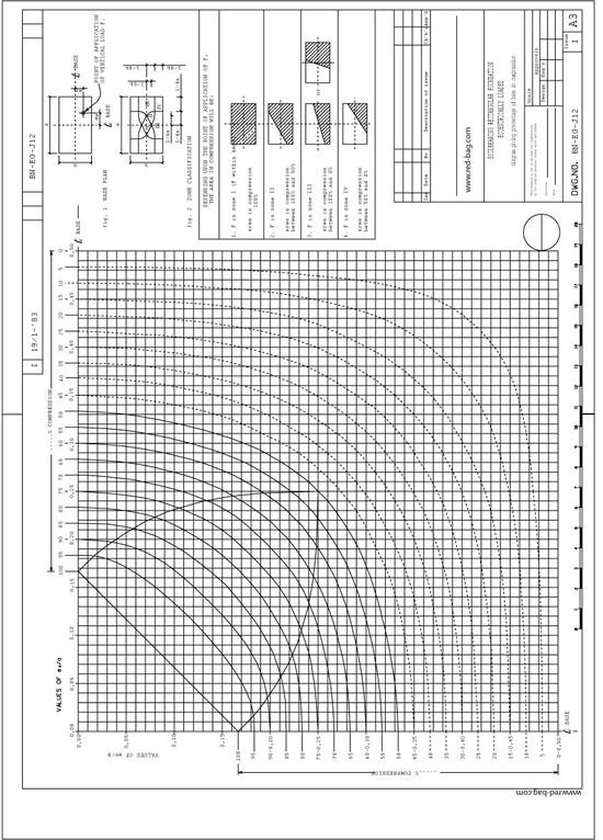
- Details
Table of Contents
- Introduction
- Scope
- General Procedure for flow diagram preparation
- The Process Flow Diagram
- The Pressure (P) - Temperature (T) Profile
- The Engineering Flow Diagrams (P&ID)
- The Utility Flow Diagram (UFD)
- The Interconnectiong Flow Diagram
- The Process Safeguarding Flow Diagram
- The Revamping Flow Diagram
- Check List
- Preparation of Line Table
- List of Related Red-Bag Standards
- List of Other Standards
- Typical Arrangement of Equipment Installation
1. Introduction
1.1 Purpose
The purpose of this document is to outline the procedures for the preparation of process flow diagrams, pressure-temperature profile diagrams, engineering, utility and interconnecting flow diagrams and special diagrams as revamp flow diagrams and pressure safeguarding flow diagrams.
1.2 Concept
Flow diagrams are highly specialized “language for information transfer. They represent the engineer’s concept of how plant equipment should be interconnected. The diagram is almost physical in a sense, since every piece of equipment, every pipeline, valve and instrument is shown. Diagrams are used to convey information between groups working on the project and translate the plant design into ‘real’ piping and equipment.
1.3 Use
By preparing the diagrams properly, the engineer can convey a great deal of technical information, quickly and accurately, with a Limited amount of paper work.
1.4 Tee of Diagrams There are 7 types of flow diagrams:
1.4.1 The Process Flow Diagram (PFD)
The PFD is developed by the Process Engineering Department. Final drafting by the Flow Diagram Squad. On this document are given the main process equipment, fluid flows, main control loops and critical valves. It is a tool for the process engineer(s) to convey information to project and specialist engineers to design the installation in detail (see fig: 6).
1.4.2 The Pressure Temperature Profile Diagram(PTP)
The PTP diagram is a document prepared by the Process Engineering Department with the purpose of providing project, control systems and piping engineers with the correct pressure and temperature correlations between the various piping systems, vessels, exchangers, etc. The document ensures that proper values are being used for preparation of data sheets, line tables and other documents as, e. g. painting systems, insulation, etc.
For PTP preparation procedures refer to Standard Specification BN-EG-UE-1 (Design guide for Pressure and Temperature profile).
1.4.3 The Engineering Flow Diagram (EFD)
On this document are shown all equipment connecting piping, utility piping, complete with control, loops and all other instrumentation, all valves a safety measures. It is the main tool for the project engineer to convey information to the piping design office and control systems engineering group for the detailed piping and control systems design (see fig: 13).
1.4.4. The Utilities Flow Diagram
This document. shows how utilities are generated and distributed from the source or supply point to the various parts of an installation. The diagram shows coon control loops, additional equipment that is deemed necessary to supply the utility as required and the safety measures necessary (see fig: 18). The diagrams shall be drawn in accordance with the geographical layout of the plant.
The diagrams are generally divided per generation activity, e.g. steam generation, inst air, cooling water, fuel oil, etc. The utility equipment shall be shown. Packaged units to be shown within, heavy dotted line.
1.4.5 The Interconnecting Flow Diagram (IFD)
These diagrams are prepared to show the interconnecting lines between various plant units and, e.g. tank farms, etc,
1.4.6 The Process Safeguarding Flow Diagram (PSFD)
This document shows the correlation of safety devices installed but indicated on separate EFD's. It “highlights” the final level of protection provided by the safety systems installed.
This document will be produced on client's request only, e.g. SIPM
1.4.7 Revamp Flow Diagram
“Revamping Flow Diagrams” shall be prepared to indicate which equipment, lines, control loops, etc. must be demolished, modified, removed or relocated, etc. in a revamping project. The existing engineering flow diagrams of a plant or unit to be revamped shall be used.
In general two sets of diagrams are to be prepared:
a) An updated existing EFD's version for demolishing purposes, RFD's.
b) New “as built” EFD's
For more details refer to Chapter 10.
1.5 Notes:
1.5.1 It must be noted that particular instructions given by client or licensor with respect to his requirements or special requirements covered by any authority decrees shall be observed.
1.5.2 If any of such rules, decrees or instructions exist, these must be mentioned in the “Project Specification”.
1.5.3 When these instruction have not been incorporated, the documents produced will be unacceptable to the client or licensor and/or authorities.
1.5.4 Where in the following text of this Engineering Procedure has been referred to other Company procedures or standards, this is only true where the Company standards are not conflicting with those mentioned under para 1.5.1.
1.5.5 To obtain maximum uniformity with regard to line thickness, lettering, symbols, etc. the drafting on vellums shall be executed by the Flow Diagram Squad.
1.5.6 There is still another flow diagram, prepared by the control systems engineering group, exclusively for use by process and control systems engineers. This flow diagram is principally a PFD on which the control system engineer indicates specific instrument physical data. The document is called; “Instrument Data Flow Sheet”. It is not further mentioned in this ‘Engineering Procedure”.
1.5.7 The examples presented in this Engineering Procedure are taken from actual jobs and include general Clients requirements. Therefore, the symbols used will not always be identical to the symbols shown on the legend sheet fig: 22.
1.5.3 On an EFD, a package unit, e.g. compressor, can be indicated with a heavy drawn block with reference to one or more vendor flow diagrams (process, lube oil, seal oil, water cooling, etc.) which can be adopted.
2. Scope
2.1 This Engineering Procedure shall be used as a standard for the preparation of process and engineer flow diagrams as outlined in para 1.4 of the Introduction.
2.2 It shall also be used to edit systematically the text for the Project Specification on the subject of flow diagram preparation.
2.3 The purpose of this Engineering Procedure is to provide the engineers with all necessary information to generate the various diagrams needed with the greatest consistency and efficiency possible.
(...)
The full procedure is available for registered users. The procedure is part of the Introduction and Basic Piping Design course at InIPED.
- Details
Table of Contents
- Orifice Plate Calculation
- Restriction Orifice Calculations
- Appendixes:
Appendix A, Calculation of Compressibility Factors
Appendix B, Flow Formula
Appendix C, Additional Specifications for Maximum Metering Accuracy
Appendix D, Conversion Formulae for Orifice Meters
Appendix E, Calculation of Meter Maximum Flow, When Orifice Bore Is Given
1. Orifice Plate Calculations
SCOPE : This standard gives instructions for the use of Company orifice plate calculation sheets :
- form B.N. -K003-1 (English Units)
- form B.N. -K003-2 (Metric Units)
GENERAL : The method of the orifice plate calculations mentioned above is based on: “Principles and practice of flow meter engineering” by
LK Spink, 8th edition, and is in accordance with AGA-ASME standards, and the AGA gas measurement committee reports numbers 2 and 3.
Moreover the draft ISO recommendation No. 532 (revised text) dated September 1964 has been used as a basis as well.
For a simplified description of the theoretical background see appendix B.
REFERENCES :
- Principles and practice of flow meter engineering L.K. Spink, 8th edition.
- Flow measurement with orifice meters R.F. Stearns, R.R. Johnson, R.M. Jackson, C.A. Larson published by D. van Nostrand Co. Inc.
- Gas measurement committee report No. 2 AGA, May 1935.
- Gas measurement committee report No. 3 AGA, April 1955, Reprint 1956).
- AGA flow constants (Foxboro)
- Draft ISO recommendation No. 532 September 1964.
INSTRUMENTATIONS : The instructions are numbered 1 to 30.
The same numbers appear on the calculation sheets for reference.
No. 1: FLUID: Fill in process fluid flowing through the orifice.
No. 2: MEASUREMENT UNITS: (see also note below)
Fillin the units of measurement in which the client requires the meter to read. These units should be agreed upon with the client and are generally specified in the applicable general specification for instrumentation. These units may be different from the units in which normal flow is given.
No. 3: BASE PRESSURE: (see also note below)
Fillin the common base pressure to which all measurements in the plant are referred. This again is to be agreed upon with the client.
Common accepted base, pressures are 14.70 psia, 760 mm Hg and 1 Kg/cm²A.
No. 4: BASE TEMPERATURES: (see also note below)
Fillin the common base temperature to which all measurements in the plant are referred.
Agreement with client necessary. Some accepted European base temperatures are:
- Liquid : 15°C or 60°F
- Gas : 0°C or 60°F
Note: See BN-SP-K1 Specification for Instrumentation.
No. 5: BASE SPECIFIC GRAVITY:
Fillin the specific gravity at base conditions as specified under Nos. 3 and 4. For liquids, the specific gravity is related to water, for gases to air. When working in metric units, liquid specific gravity is related to water at 15°C (density of water at 20°C is 0.99823 grams/cm³).
The specific gravity of gases can be obtained by dividing the molecular weight of the gas by the molecular weight of air (28.996).
For English Units the specific gravity is referred to water at 60°F.
No. 6: STEAM QUALITY:
Fillin quality of the steam, and when it is superheated or saturated, state this.
No. 7: NORMAL FLOW AT BASE CONDITIONS:
Fillin the normal flow at base conditions as specified and the units in which it is given.
No. 8: NORMAL FLOW IN WEIGHT UNITS:
Fillin the normal flow rate and the units in which this is given.
No. 9 and 10: METER MAXIMUM FLOW:
Fillin meter maximum flow after calculations as outlined under 27.
No. 11: MINIMUM FLOW:
If the minimum flow falls below 20% of the meter maximum flow, consideration should be given to the use of a second lower differential range instrument or a second orifice run.
No. 12: COMPRESSIBILITY:
Fillin the compressibility ratio’s Zb, Zf for gas flow which are defined as:
Zf = deviation from true gas law at operating conditions.
Zb = deviation from true gas law at base conditions.
The compressibility ratio’s can be determined from reduced pressure and reduced temperature as outlined in Spink, pages 351 and 352. See also appendix A.
No. 13: MOLECULAR WEIGHT:
Fillin molecular weight for gas flow only.
No. 14:OPERATING PRESSURE:
Fillin upstream pressure in psia or Kg/cm² Abs.
(Kg/cm²A = Kg/cm² gauge + 1.0336).
(PSIA = 14.70 + psig).
No. 15:OPERATING TEMPERATURE:
Fillin the operating temperature at the orifice in degrees Rankine for the English calculation sheet and degrees Kelvin for the metric calculation sheet (°R = °F + 459.6, °K = °C + 273.2).
No. 16: OPERATING SPECIFIC GRAVITY:
Fillin specific gravity at operating conditions. For liquids this specific gravity is referred to water of 60°F, when working in English units and 15°C when working in metric units.
No. 17: OPERATING DENSITY:
The operating density is in some cases to be found in tables such as the steam table but in other cases must be calculated as out-lined under 27.
No. 18 ABSOLUTE VISCOSITY:
The operating viscosity shall be given in centipoises. Viscosities of several liquids are given on pages 325 thru 331 of “Flow measurement with orifice meters” published by D. van Nostrand Co. Inc. or page 184 of “Principles and practice of Flow Meter Engineering” by L.K. Spink.
To convert from centistokes to centipoises multiply by the specific gravity. For other conversions see page 311 thru 324 of the Van Nostrand book.
No. 19: METER DIFFERENTIAL: (h)
A meter differential of 100 ins W.G., or its metric equivalent is preferable. To avoid swaging up higher ranges 150” W.G., 200” W.G., etc., may be used.
For compressible fluids, the range in inches water should be lower than the absolute static pressure, (at upstream side), this to keep the Y factor (see 29 III) within reasonable limits.
For computer calculations these values are:
- gas : (in H2O) = 1.3 upstream pressure
- steam : (in H2O) = 2 upstream pressure
No. 20: NOMINAL PIPE SIZE AND SCHEDULE:
Fill in the nominal size of the pipe, and the schedule (see piping specification).
If the pipe size is given to DIN standards, fill in outside diameter and the wall thickness. (When the form English units is used, state also the inside diameters in mm).
No. 21: ACTUAL I.D.:
The internal diameter as given in line tables and the square of this figure shall be stated in units as indicated.
When the form for English units is used, and the pipe is to DIN standards, fill in I.D. in inches, converted from I.D. in mm. stated in 20.
No. 22: CHART GRADUATION AND CHART FACTOR:
A chart graduation shall be specified preferably 0-10 or 0-100 square root.
This should be agreed upon with client. In special cases, a direct reading graduation may be used.
The chart factor is the rounded off meter maximum flow divided by the maximum chart reading.
No. 23: PRESSURE TAKE-OFF LOCATION:
When the static pressure measuring point has been specified, state if pressure is taken-off from upstream or downstream tapping. This in connection with the use of diagrams for expansion coefficient. (See 29, correction III).
It is Company’s standard practice to take off the pressure from the upstream tapping, as specified in the ISO standard no. 532 (Draft recommendation). Pressure measured at downstream tapping may be considered, when the static pressure is very low, so that the rule of thumb as mentioned is no. 19 page 7 can not be followed.
( ... )
The full procedure is available for registered users.