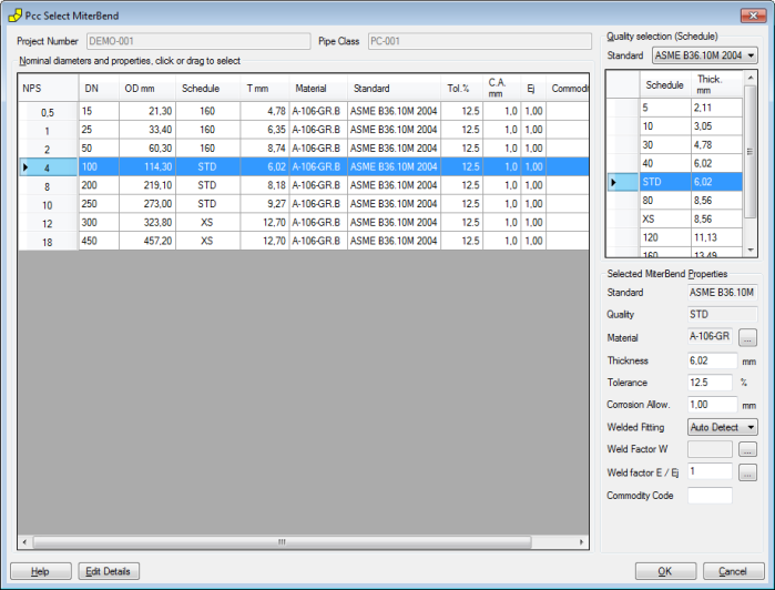
The miter bend dialog window is opened by selecting in the menu 'Tables' > 'Miter bend'. The data for the miter bends is selected in this dialog.
When selecting a miter bend, the data for each miter bend is retrieved from the standard components that are part of the database. The detail dimensions can be modified to suit custom made components.
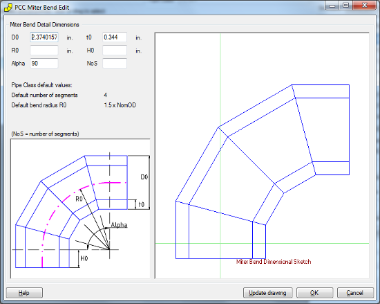
At the bottom of above dialog click the button 'Edit details', a new dialog will be shown. The right frame in the dialog will be empty at first instance, click the button 'Update drawing' to show the dimensional sketch in the right frame. The following dialog shows an example.
The various dimensions can be edited by the user. An example is shown below.
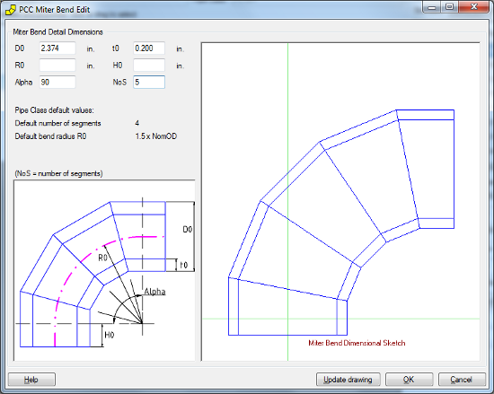
In the dialog the edit options are as follows:
- 'D0', outside diameter of miter bend
- 't0', wall thickness at miter bend ends
- 'R0', (mean) radius of miter bend at centerline
- 'H0', extra height outside radius
- 'Alpha', total angle of miter bend
- 'NoS', the number of segments
At the bottom of the dialog:
- 'Help' button, to show this help page.
- 'Update drawing' button, to update the right frame based on the user input.
- 'OK' button, to save the data to the pipe class database and close the dialog.
- 'Cancel' button, to close the dialog without saving the data.