Input variables
Generic variables
These variables can be found in virtually all reports as input variables
- Gas infrastructure
- Location of the facility near which the gas infrastructure is situated.
- Underground, except a station
- In a tunnel
- Station
- Maximum Design Factor – fo
- Factor for restricting the allowable stress. The value can be chosen smaller, but not larger.
- Design Pressure – DP
- Pressure assumed to be present in the component according to the design terms
- Design Temperature – θ
- Temperature assumed to be present in the component according to the design terms
- Material
- Name of selected material used for the construction of the component
Specific variables
These variables are component specific
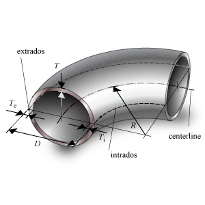
- Outside Diameter – D
- Outside diameter of the attached part. The diameter runs from the outside of the wall to the opposite outside of the wall, through the center of the circle.
- Nominal Thickness neutral line – Tn
- The neutral line is along the neutral axis of the bend. Thickness ‘as is’, meaning it is the design thickness taking into account corrosion and tolerance.
- Nominal Thickness Intrados – Tin
- Intrados is the inner radius of the bend. Thickness ‘as is’, meaning it is the design thickness taking into account corrosion and tolerance.
- Nominal Thickness Extrados – Ten
- Extrados is the outer radius of the bend. Thickness ‘as is’, meaning it is the design thickness taking into account corrosion and tolerance.
- Corrosion – Ca
- Amount of thickness that accounts for the possible effects of corrosions.
- Tolerance – tol
- Tolerance in thickness for production
- Strength reduction coefficient – z
- Effectiveness of the strength, depending on whether joints are seamless, welded, or expected to perform worse than the base material properties
- Bend Radius – R
- Radius of the bend from the origin to the neutral axis of the bend. The origin lies in on the intersection of the lines perpendicular to neutral axis, through the points where the bend ends turn straight
Bend
Calculated Values
- Yield strength at operating temperature – Rt
- Stress in the component at which the component starts to plastically deform at operating temperature.
- Minimum yield strength at 20 °C – Rta
- Stress in the component at which the component starts to plastically deform at 20 °C ambient temperature
- Allowable Operating Stress – S
- Stress in the component at which it is still allowed (without failure) to use the component
- Allowable stress at 20 °C – St
- Stress in the component at which it is still allowed (without failure) to use the component at testing condition
- Intrados factor – Ci
- Bend correction factor at the inner radius of the bend (bend radius − half the outside diameter)
- Extrados factor – Ce
- Bend correction factor at the outer radius of the bend (bend radius + half the outside diameter)
- Nominal Required Thickness neutral line, intrados, extrados – Trn, Tirn, Tern
- Based on the input, this is the calculated thickness that is required to sustain the loads. The nominal value should be smaller than the nominal design thickness.
- Maximum Allowable Working Pressure – MAWP
- The maximum pressure at which the component can be used in operation. This value should be larger than the design pressure.
- Design margin – DP / MAWP
- Ratio of the design pressure to MAWP
- Maximum Allowable Test Pressure – MATP
- The maximum pressure at which the component should be tested and survive.
Scope errors
- Design pressure is out of scope: minimum operating pressure > 16 bar.
- This code determines a minimum pressure.
- Design temperature is out of scope: required -40 °C ≤ T ≤ 120 °C.
- This code determines a minimum and maximum temperature.
- Design factor is too large: required is fo ≤ fomax (see 7.2).
- This code determines a maximum design factor.
- Wall thickness (neutral line) is out of scope according paragraph 7.9.2 Table 1.
- This code determines for bends a minimum thickness.
Errors
- Can’t find material ‘MaterialName’ in database
- Material could not be found in database. Select an existing material name, or select another material via the material selection window.
- Insufficient wall thickness neutral line.
- Wall thickness is insufficient to bear the applied loads. Increase the wall thickness at the neutral line.
- Insufficient wall thickness intrados.
- Wall thickness is insufficient to bear the applied loads. Increase the wall thickness at the intrados. The intrados should generally be thicker than the minimum required thickness at the neutral line.
- Insufficient wall thickness extrados.
- Wall thickness is insufficient to bear the applied loads. Increase the wall thickness at the extrados. The extrados should generally be thinner than the minimum required thickness at the neutral line.
Remarks
- Sufficient bend radius for field bends according paragaph 9.2.8.2.
- This code allows to use a field bend.