Input variables
Generic variables
These variables can be found in virtually all reports as input variables
- Location Class – Location Class
- The physical location of the component marked with a classification.
- Facility – Facility
- The facility under or near which the component is located.
- Test medium – Test medium
- The medium used to test the component
- Design Pressure – P
- Pressure assumed to be present in the component according to the design terms
- Design Temperature – Td
- Temperature assumed to be present in the component according to the design terms
- Material
- Name of selected material used for the construction of the component
Specific variables
These variables are component specific
- Outside Diameter – D
- Outside diameter of the attached part. The diameter runs from the outside of the wall to the opposite outside of the wall, through the center of the circle.
- Nominal Thickness – tn
- Thickness ‘as is’, meaning it is the design thickness taking into account corrosion and tolerance.
- Corrosion – Ca
- Amount of thickness that accounts for the possible effects of corrosions.
- Tolerance – tol
- Tolerance in thickness for production
- Joint Efficiency – E
- Effectiveness of the strength, depending on whether joints are seamless, welded, or expected to perform worse than the base material properties
- Length tangent to tangent – L
- Length of the straight part of the pipe (equals the unsupported length of the pipe)
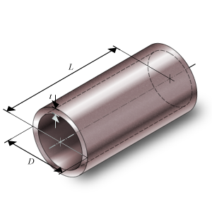
Pipe
Calculated Values
- Minimum yield strength at 20 °C – S
- Stress in the component at which the component starts to plastically deform at 20 °C ambient temperature.
- Design factor – F
- Factor for the allowable stress when considering underthickness tolerance and maximum allowable depth of imperfections.
- Temperature derating factor – T
- Factor for the allowable stress when considering high design temperatures.
- Test design factor – Ft
- Factor for the allowable stress when considering underthickness tolerance and maximum allowable depth of imperfections.
- Nominal Required thickness – trn
- Based on the input, this is the calculated thickness that is required to sustain the loads. The nominal value should be smaller than the nominal design thickness.
- Maximum Allowable Working Pressure – MAWP
- The maximum pressure at which the component can be used in operation. This value should be larger than the design pressure.
- Design margin – P/MAWP
- Ratio of the design pressure to MAWP
- Test pressure factor – FPt
- Factor for maximum test pressure based on design pressure.
- Maximum Allowable Test Pressure – MATP
- The maximum pressure at which the component should be tested and survive.
- Required Test Pressure – Pt
- Required hydrostatic pressure for testing at any point in the piping system (paragraph 841.32)
Scope errors
- Temperature is out of scope: minimum temperature = -29 °C
- This code determines a minimum temperature.
- Temperature is out of scope: maximum temperature = 232.22 °C
- This code determines a maximum temperature.
Errors
- Can’t find material ‘MaterialName’ in database
- Material could not be found in database. Select an existing material name, or select another material via the material selection window.
- Insufficient wall thickness
- Wall thickness is insufficient to bear the applied loads. Increase the wall thickness.