(Full title: Specification for Electronic Model Transfer and General Arrangements)
Table of Contents
1. Introduction
2. Electronic Model Transfer to Contractor
3. General Arrangement Drawings by Contractor
4. Attachments
1.Introduction
This specification describes a procedure for electronic model transfer of 3D steel models between Purchaser and Contractor and the requirements for necessary drawings to be created by Contractor. It is the intention to achieve a quality improvement of work and a more time efficient working method.
2.Electronic Model Transfer to Contractor
2.1 General
All structural steel items will be designed as three-dimensional steel models by Purchaser. Each steel structure will be one model. The three dimensional steel models form part of Purchaser’s electronic Plant Design System (PDS) which also includes designs from other disciplines like piping, equipment, civil, electrical and instrumentation. Only structural steel information will be transferred to Contractor. As modeling tool for structural steel Intergraph’s FrameWorks Plus is used.
2.2 Neutral File
Except for circular members (i.e. circular platforms), all Purchaser’s three-dimensional steel models will be translated into a Neutral File. This Neutral File shall be converted by Contractor into a three dimensional model in STRUCAD or BOCAD. This implies that Contractor’s steel models are fully conform Purchaser’s steel models and ensures full and adequate Quality Control. Connection details shall be added by Contractor. The electronic model information flow is a one way flow from Purchaser to Contractor. No changes to steel models other than fabrication details are allowed without previous written approval by Purchaser. Workpoint location, orientation and section sizes of steel members including horizontal and vertical bracing must be maintained.
Floppy discs, CD-ROM’s or Electronic mail will be used for file transfer.
2.3 Model Contents
Purchaser’s steel model can contain columns, beams and braces, but also stairstringers, moment connection locations, ladder locations and fireproofing. Furthermore drawings will be issued by Purchaser with additional detailed information, when required.
All models are defined in metres, and are located at client’s plant coordinates. Each model has a unique location.
2.3.1 Stairstringers
Stairstringers are modelled correctly by Purchaser except for connections. Connections shall be detailed by Contractor according to the applicable specifications and standards. Stairtreads and workpoints will not be included in the model, but can be found on a drawing which will be issued together with the neutral file by Purchaser.
2.3.2 Moment Connections
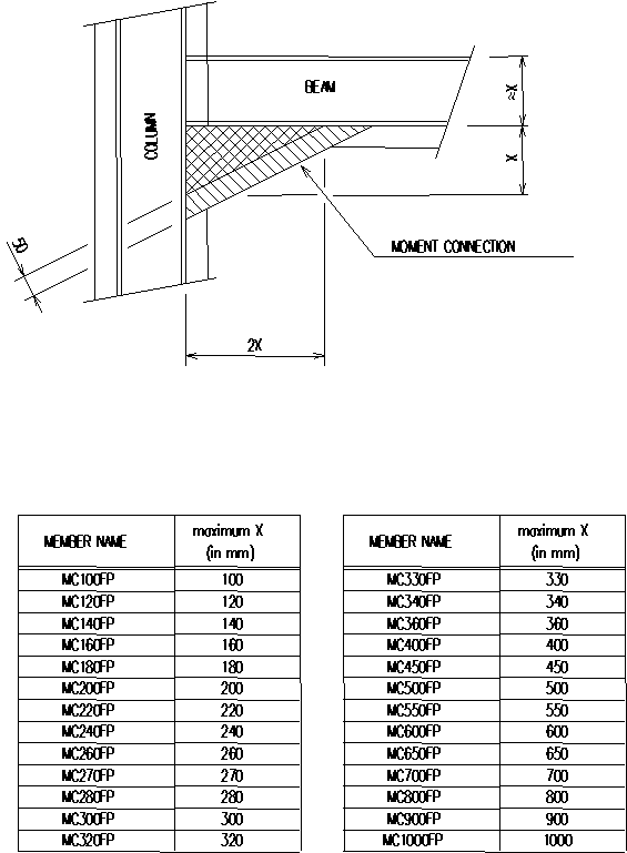
Moment connection locations are modelled for information only. These ‘members’ shall be replaced by detailed connections by Contractor, but Purchaser’s space reservation for these connections shall not be extended unless written approval is given by Purchaser. For moment connection member name convention, see attachment I.
2.3.3 Ladders
Ladders are also modelled for information only. The location of centreline of rungs is correct but rung width, rungs centre to centre distance, ladderstringers and cages shall be detailed by Contractor according to the applicable specifications and standards.
2.3.4 Fireproofing
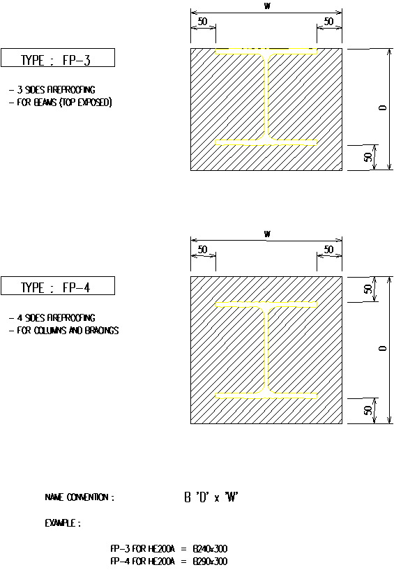
Fireproofing is modelled as ‘concrete’ members over the relevant steel members by Purchaser. The concrete members indicate the surface of the steel members which shall be treated for fireproofing according to the applicable specification. Concrete may also be lightweight fireproofing or as specified. For fireproofing (concrete member) name convention, see attachment II.
2.3.5 Drawings by Purchaser
Drawings with additional details will be issued by Purchaser, which shall be read in conjunction with the steel model, since not all information can be translated into a neutral file.
There are two types of drawings:
-
General arrangement drawings
-
Drawing sketches
General arrangement drawings
General arrangement drawings will be issued by Purchaser with document status ‘Released For Construction’. From these drawings all design information can be obtained. The Neutral File, which will be issued together with these drawings, shall be used as the design base by Contractor. In case of any discrepancies between drawings and Neutral File the latter shall govern.
Drawing sketches
Drawing sketches will be issued by Purchaser with document status ‘Released For Design’, and shall be read in conjunction with the Neutral File since not all design information can be translated into the Neutral File. If drawing sketches are issued by Purchaser, Contractor shall create the general arrangement drawings as described in chapter 3 of this specification.
Information on drawing sketches can be:
-
a complete 3D picture of the entire structure;
-
baseplate plan with grid labels if applicable and north & east plant coordinates as reference;
-
a north arrow;
-
outlines of all floor and platform areas covered with grating or raised pattern plate with size and location of piping and/or equipment penetrations;
-
handrailing (with cut outs);
-
equipment supporting details;
-
location and membersize of existing steel;
-
location and sizing of connecting concrete structures;
-
location and details of connections to concrete structures;
-
stair workpoints and number of stairtreads;
-
special details (e.g. connections, sheeting);
-
‘Holds for’ in model;
-
text notes.
3. General Arrangement Drawings by Contractor
3.1 General
For a selected number of steel items (see attachment III), mainly equipment supporting structures, piperacks and buildings, it is the purpose for Contractor to create General Arrangement drawings as deliverables, using STRUCAD or BOCAD as a modeling tool and AUTOCAD or MICROSTATION as drafting tool.
Purchaser’s Neutral File and drawing sketches, together with information from the applicable specifications and standards, shall be used for preparation of Contractor’s documents. Contractor shall carefully study the design information and discuss with Purchaser any queries or discrepancies within each or between any of these prior to the commencement of the work.
It is allowed to combine the general arrangement drawings and the markplans.
3.2 Drawing lay-out
In order to meet Purchaser’s quality standard, General Arrangement drawings for steel structures shall show the following information:
-
a complete 3D picture of the entire structure including the static system i.e. bracing and moment connections;
-
baseplate plan with grid labels if applicable and north & east plant coordinates as reference;
-
a north arrow;
-
all plans and views;
-
all member sizes;
-
all members in plans to be dimensioned from reference points (grids);
-
all horizontal members in views to be dimensioned with elevations (elevation deviations in plans from nominal TOS elevation);
-
dimensions in millimetres and elevations in metres or millimetres;
-
showing extent of fireproofing graphically (preferably 3D pictures of fireproofed members only) and by marking members with FP-3 for three sided fireproofing or FP-4 for four sided fireproofing;
-
outlines of concrete frames and concrete structures;
-
cross references to other drawings (e.g. baseplate details, equipment connections);
-
client’s or purchaser’s drawing border, including a correct filled in title block, contractor‘s identification and a completed ‘VPC’ sticker (see attachment ‘Vendor Furnished Documents’ in requisition, SE30 REQ);
-
general notes (e.g. instructions and/or restrictions for erection);
-
material qualities and surface treatment.
For graphical explanation of General Arrangement drawing layout see attachment IV.
3.3 Document Review
When purchaser’s neutral file and drawing sketches are issued, these documents will reach the status ‘Released For Design’. Although it is purchaser’s intention to issue complete design information, contractor shall accept changes and/or additions to these documents, as continued plant design developments may cause such.
In order to timely incorporate this additional information in contractor’s documents, purchaser will indicate same on contractor’s first (for review) issued drawings (and other documents if required) and will issue an updated neutral file of purchaser’s model where applicable.
Above changes may involve the following items:
-
additions and/or relocations of floor beams;
-
additional pipe supports;
-
changes/additions in platform requirements;
-
additional information on cuttings in gratings;
-
railing modifications.
After the Contractor has received the first (for review) issued drawings with Purchaser’s comments, possibly above-mentioned additional information and updated Neutral File, the structural steel design will be frozen. Still the Contractor has to incorporate the comments and changes on the General Arrangement drawings before these documents reach the status ‘released for construction’. These drawings shall be handed over to Purchaser who will sign for acceptance.
3.4 ‘As Built’ Drawings
Drawings of structural steel items that shall have the final issue ‘As Built’ are mentioned in attachment III. This issue comes on top of the drawing issue ‘released for construction’ and shall show the complete steel items, including structural steel erection modifications.
4. Attachments
| I |
Moment Connection Name Convention |
2 shts. |
iss:1 |
| II |
Fireproofing Name Convention |
1 sht. |
iss:1 |
| III |
List of General Arrangement Drawings by Contractor |
1 sht. |
iss:1 |
| IV |
General Arrangement Drawing Layout |
1 sht + |
iss:1 |
Moment Connection Name Convention
(without fireproofing)
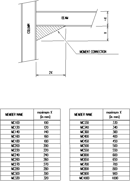
Moment Connection Name Convention
(with fireproofing)
Fireproofing Name Convention
List of General Arrangement Drawings by Contractor
|
Document No. |
Description |
‘As-built Dwgs.’ (yes or no) |
|
|
1. |
|||
|
2. |
|||
General Arrangement Drawing Layout
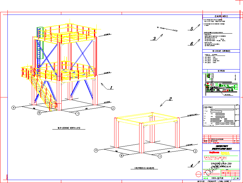
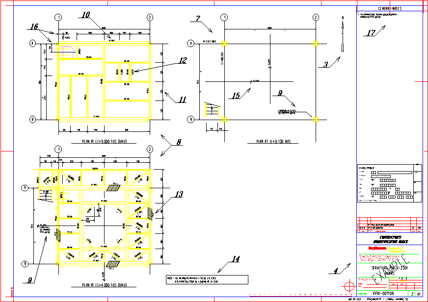
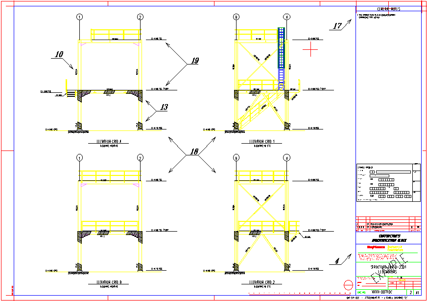
This attachment gives a graphical explanation of the general arrangement drawing lay-out, which is presented in example drawings “A”, “B” and “C”. On these drawings annotation numbers are shown, which are defined underneath.
Annotation numbers definition:
| 1. |
A complete 3D picture of the entire structure, including grid labels, grid distances and main elevations. |
| 2. |
A 3D picture of fireproofed members (if applicable), including grid labels, grid distances and main elevations. |
| 3. |
North arrow. |
| 4. |
Correct filled in title block (dictated by Purchaser), Contractor’s identification and a completed VPC sticker. |
| 5. |
General notes for the “A” drawing including reference drawings, keyplan and account code, dictated by Purchaser. |
| 6. |
Material qualities and surface treatment. |
| 7. |
Baseplate plan with grid labels and north & east coordinates as reference. |
| 8. |
All structural plans shall be shown. |
| 9. |
Cross-references to other drawings (in principle dictated by Purchaser). |
| 10. |
All member sizes shall be shown. |
| 11. |
All members shall be dimensioned from reference point (grids) in millimetres. |
| 12. |
Elevation deviations of members in comparison with plan title elevation (in millimetres). |
| 13. |
Fireproofed members shall be shown. |
| 14. |
Special notes, in principle dictated by Purchaser. |
| 15. |
Main equipment centrelines and dimensions, dictated by Purchaser. |
| 16. |
Ladder rung location shall be dimensioned. |
| 17. |
General notes for drawings other than the “A” drawing, dictated by Purchaser. |
| 18. |
All structural main views (on grids) shall be shown. |
| 19. |
All horizontal members in views to be dimensioned with elevations preferably in metres. |
Drawings belonging to attachment IV:
- Example drawing “A”
- Example drawing “B”
- Example drawing “C”
