
")
Table of Contents
1. Purpose
This procedure describes the format, method, preparation and control of engineering calculations.
2. General
This procedure sets out the practice to be followed for the preparation of calculations and covers those calculations involved in the safety and integrity of the plant and those calculation where failure would result only in local inconvenience i.e. calculations not involving the safety and integrity of the plant. The Company policy on safety in design is set out in the procedure reference 6.1 which is considered to be part of this procedure. This procedure ensures that consistent, up-to-date, standards of calculation preparation, checking and approval are maintained, which adds to the quality of all calculations produced and shall apply to all projects.
3. Responsibility
3.1 The Manager of Engineering has the overall responsibility to ensure that qualified Group Managers, Engineering and Designers, along with appropriate means, are available.
3.2 The Group Managers/Section Leaders are responsible for setting-up and maintaining standardized methods of calculations, reference standards and authorization of computer programs (ref. 6.4).
3.3 The Lead Specialist Engineer/Lead Designer on a project are responsible for the preparation and control of engineering calcula tions.
3.4 The Engineers and Designers assigned to a project are responsible for preparing the original calculations and their accuracy.
4. Procedure
4.1 Principles of Calculation Preparation
All calculations shall be prepared to a standard that would allow them to be submitted to an independent checking authority.
If a checking authority is involved for the work then:
Any particular requirements of the checking authority shall be established prior to the start of the calculations.
Calculations shall be clearly presented without ambiguity and each set or type of calculations shall be indexed.
The design information upon which the calculations are based shall be clearly stated and any assumptions or references used shall be clearly identified.
Notations used in the calculations shall be consistent and in accordance with the national regulations or the notations in common use in the industry.
The setting out of calculations shall follow a consistent pattern.
The engineering approach to the calculations shall be clearly thought through before the calculations are started.
The calculations shall be prepared such that in the event of illness or other absence another engineer or designer could complete the work after a simple review of the calculation information.
The final calculation presentation shall be such that the calculations may be clearly understood without further explanation at any time by Company personnel or a third party, e.g. in modification or additional work.
Any revisions to the calculations after they have been checked/app roved shall be recorded as issue II or III progressively together with the date of the change both individually on the sheets affected and collectively on the cover and index sheets for manual calcula tions and on the cover sheet for computer calculations. Any revised sheets shall be subjected to the full checking and approval sequence required by this procedure for the particular category of the calculations concerned.
4.2 Format
4.2.1 Calculation Sheets
Manual calculations shall be prepared on the standard calculation work sheet "BN-U202"
An index of calculation sheet issues, (see below figures, 'Index of calculation sheet issues') shall be used on sheet (see below figures 'First Formal Issue') with those calculations of a multi-sheet type where it is anticipated that revisions and/or additions will take place thus avoiding the need to make a total issue of all sheets for revised issues.
An cover sheet (form US778-01) shall be used on all calculations.
4.2.2 Identity of Calculations
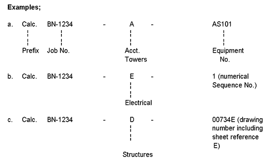
The cover sheet of the calculations shall bear an identification number and shall show the title and the subject of the calculation.
Identification of calculations shall be by the inclusion of a prefix "calc", the job number, an account letter and a calculation number.
This applies to both manual and computer type calculations.
Account letters shall be as follows:
| A | - Towers |
| B | - Buildings |
| CG | - Piping, General |
| CS | - Piping Stress/Supports |
| D | - Structures |
| E | - Electrical |
| F | - Fire Protection |
| G | - Special Equipment |
| H | - Fired Heaters and Stacks |
| J | - Foundations, Paving, Excavation, etc. |
| K | - Instrumentation |
| M | - Drums, Tanks and Reactor |
| N | - Insulation |
| P | - Pumps, Compressors, Eductors |
| Q | - Sewers and Drains |
| R | - Painting |
| S | - Site Development and Special Concrete Work |
| T | - Heat Exchangers |
The calculation number shall take regard of the varying requirements of the groups. For instance, data related to a tower shall be identified by its equipment number, electrical calculations can be a simple numerical sequence whereas a structure would be related to a drawing number.
4.2.3 Completion of Calculation Sheet Issue Blocks
The Engineers/Designer (originator) shall complete the heading of each calculation sheet and print his name under "signature". The Engineer/Designer and checker shall initial the issue block on the cover sheet.
"Safety" type calculations shall be approved. (See section 4.4)
For "nonsafety" type calculations approval is not required (see section 4.5). The checker shall add a diagonal line across all approval blocks.
Where project conditions require the endorsement of calculations by "others" such as the Project Manager, this shall preferably be indicated by his also initialing the approval block.
Where project conditions require the certification of a calculation, the certification block shall be completed by the Lead Specialist Engineer and the Project Manager.
4.2.4 Setting Out and Content of Calculations
Manual Calculations The size of lettering used on all manual calculations shall be minimum 2.5 mm. All calculations shall be legible and shall be suitable for microfilming. The heading of each of the calculation sheets shall be fully completed at the start of each new sheet.
All calculations are to be made on the company standard calculation sheets BN-U202 or alternative on Client's standard calculation sheets if this is a requirement of the project.
Each set of calculations shall have a follow sheet setting out allowable design materials, stresses or parameters taken from the project design specification or codes of practice and the derivation of any formulas or technical references used in the calculations.
This follow sheet may be a standard calculation sheet or a proforma follow sheet specific to a particular group or department.
Where necessary the calculations shall contain a clear dimensioned design sketch of the problem to be solved. The design sketch shall preferably be to scale or where this is difficult to achieve shall be diagrammatically set out to clearly show the main design fea tures. Reference points such as node numbers used in the calculation shall be shown on the design sketch.
The calculations shall be set out such that following steps are easily apparent to a third party:
a. Input - i.e. design problem information related to temperatures, loading or imposed force
b. Derivation - mathematical calculation to arrive at results
c. Results - the results of the mathematical calculation and their interpretation into engineering details.The results shall be clearly displayed by underlining or other means so that they are easily identifiable in the body of the calculations.
The units of measurement, stress force or similar shall be consis tent throughout the calculations and preferable throughout the project.
The symbols associated with measurement, stress, force or similar shall be as set out in the Project Procedure Manual or as currently used in the standards or accepted in the industry.
Computer Calculations
The preparation of the headings for calculations produced by computer shall follow the requirements as set out for manual calculations.
The computer run results shall, where required, print out a diagram of the problem to be solved to replace the calculation sketch that is provided for manual calculation. Referance points as node numbers used in the calculation shall appear on the diagram print out.
The Engineer/Designer's name shall appear on the computer print out.
The program name/number/issue identity shall appear on the computer print out.
The input shall contain the allowable design materials, stresses or parameters taken from the project design specification to provide equivalent information to the lead sheet requirements of manual calculations.
The date of the computer run shall appear on the print-out.
The hard-copy print out shall be suitable for final print out at A4 size either by direct print-out or by reduction where the number of characters per line dictates.Hard copy on two part paper may be used where it is considered appropriate for use as additional copies to be issued to an authorizing authority.
Only programs which are authorized by the Group Manager and/or which can be substantiated to an authorized authority shall be used. (Ref. 6.4) The hard copy shall be a complete record of the input and the output.
Any manual calculations produced in association with the computer print-out for interpretation of the results, etc., shall be prepared to the standard required for manual calculations as set out in this procedure, and shall form a part of the computer calculation.
4.3 Category of Calculations
Calculations shall be considered to be in the following categories for all projects.
4.3.1 Calculations Involving the Safety and Integrity of the Plant
(denote "safety type")
Structural calculations
Civil calculations except site development cut and fill balances
Drainage calculations except sanitary sewers and sewers carrying rainwater only
Pressure vessel and exchangers calculations
Piping engineering calculations
Pipe support and pipe stress calculations
HVAC calculation for control rooms or other critical equipment.
Electrical calculation for:
- System fault level studies
- Protection coordination
- Earthing leakage protection
- For MV substations, particularly outdoors
. System earthing
. Clearances
. Insulation levels
- Cable rating and sizing
Instrumentation calculations for:
- Sizing of safety relieving devices (e.g. relief valves)
- Intrinsically safe installation loop parameter check
- Restriction orifice, dependent on application
4.3.2 Calculations not Involving the Safety and Integrity of the Plant(denotes "nonsafety type)
Drainage calculations for sanitary sewers and sewers carrying rainwater only
Civil calculations for site development cut and fill balances
HVAC calculations for offices, workshops and similar nonessential facilities
Electrical lighting
Instrument calculation for:
- Flow measurement (e.g. orifice plates)
- Control valve sizing
- Level measurement (differential pressure cell range/elevation/suppression)
- Vortex shedding frequency (thermowells, analyzer probes)
- Instrumentation air and overall electrical power consumption
- Restriction orifice, dependent on application
- Cable routing and sizing/rating.
4.4 Safety Type Calculations
4.4.1 Checking of Calculations
General
The main points for checking of calculations shall include but not be limited to:
- Input
. Validity/completeness of reference data
. Applicable of reference codes
. Stipulation of assumption, default values
. Any other relevant information
- Method(s)
. Verification of correct formulae, correction factors
- Output
. Make sure that the results are accurate/realistic by means of applying an alternative method(s), using "common sense", comparing results with past experience etc.
- Changes
. All changes after the formal issues are to be recorded and identified. (Ref 6.6).
. Execution to be carried out in due time to avoid adverse downstream consequences.
Manual Calculations
All manual calculation produced on a project shall be fully checked.
The checker shall carry out a complete theoretical and mathematical check of the calculations.
The check shall be carried out on a check copy of the calculations. Any corrections required by the checker shall be marked on the check copy in such a manner that they will be clearly understood.
The checker shall be satisfied that the setting out of the calculations, the completion of the page heading, the sheets numbering and the issue date is all in accordance with the requirements of this procedure.
The theoretical check shall include the design approach used to solve the problem including any design assumption, the correctness of any formulas, the acceptance of their authority, and the correct interpretation of any design references.
The mathematical check shall include a check on the derivation of the loadings, dimensions, stresses, temperatures, liquids, materials, etc., which the designer has decided comprise the problem to be solved, and a complete check on all arithmetic within the calculation.
The checker shall be satisfied that the design logic used will provide an economic solution to the problem which is consistent with the safety requirements and practical considerations of construction, fabrication and operation.
The checker shall check that the interpretation of the calculation results into design elements is correct and logical and consistent with the safety requirements and practical considerations of fabrication, construction and operation.
If during the course of checking the checker finds a mistake which requires a major revision to the calculations, the checking shall stop and the calculations shall be returned to the engineer/designer for correction. When the revised calculations have been prepared the checking process shall be recommenced.
If the checking process has uncovered only minor mistakes the copy of the checked calculation shall be returned to the engineer/ designer for corrections, after the whole document checking is completed.
After the checker is satisfied that all the calculation sheets have been corrected in accordance with the check requirements, the issue block on the cover sheet will be completed in accordance with the requirements of this procedure (see below figures 'First Formal Issue').
Computer Calculations
All calculations produced by computer shall be checked as follows:
The checker shall investigate the program selected by the engineer/designer and shall be satisfied that the program is suitable for the calculations to be carried out.
The checker shall be satisfied that the print out provides all the information required by this procedure for the setting out and content of computer calculations.
The theoretical check shall include the design assumptions and the derivation of the loadings, dimensions, stresses, temperatures, liquids, materials, etc., which the originator has decided comprise the problem to be solved.
The checker shall be satisfied that the design logic used will provide an economic solution to the problem which is consistent with the safety requirements and practical considerations of construc tion, fabrication and operation.
The checker shall pay particular attention to the correct interpretation of the sign convention for positive and negative values, and clockwise and anti-clockwise rotations where appropriate.
The checker shall not be required to check the mathematical accuracy of the calculation content of the output unless a result is found to be suspicious.
The checker shall check the interpretation by the originator of the computer output results and the translation into design elements and ensure they are logical and consistent with the safety requirements and practical considerations of fabrication, construction and operation.
If during the course of the checking the checker finds a mistake which requires a major revision to the calculations, the checking shall stop and the calculations shall be returned to the originator for revision. When the revised calculations have been prepared the checking process shall be recommenced.
After the checker is satisfied that the calculations are correct the issue block on the cover sheet shall be signed/initialled and dated in accordance with the requirements of this procedure. (See below figures 'First Formal Issue').
4.4.2 Approval of Calculations
Manual and Computer Calculations
The approval of calculations shall be carried out by an authorized person in accordance with the definitions and requirements of procedure ref. 6.3 (see below figures 'First Formal Issue').
The approval of calculations is limited to the approval of the originator's understanding of the problem to be solved, the design principles adopted and that the results have been satisfactorily interpreted i.e. is the answer a satisfactory solution to the problem and have all the necessary design cases been satisfactory investigated.
The person approving the calculations shall not be responsible for checking the arithmetic of the calculations which shall have been carried out during the checking stage. The person approving the calculations shall review them against the final drawings or other final documents as appropriate.
The person approving the calculations shall pay particular attention to the safety aspects involved and the correctness of the origin ator's interpretation of the induced loads, stresses, etc.
If the person approving the calculation is not satisfied with the calculation standard or the results or considers that additional design considerations are necessary the calculations shall be returned to the Lead Engineer and the approver's recommendations incorporated or otherwise agreed. The checking and approval sequen ces shall then be recommended.
When the person approving the calculations is satisfied with the calculations they shall be signed/initialled and dated in accordance with the requirements of this procedure. (See below figures 'First Formal Issue').
4.5. Nonsafety Type Calculations
4.5.1 Checking of Calculations
Manual and Computer Calculations
The checking of calculations not involving the safety and integrity of the plant shall be limited to a review of the originator's understanding of the problem to be solved, the design principles adopted, the designer's satisfactory interpretation of the problem, the input and the calculation results.
The persons checking the calculations shall not carry out a mathematical check unless the checker is not satisfied that the calculated results are a reasonable and economic solution to the problem.
If in the opinion of the checker the calculations are not satisfactory they shall be returned to the originator and the checking process restarted after the corrections have been carried out.
After the checker is satisfied that the calculations are correct the cover sheet of manual calculations and the front sheet of the hard copy of computer calculations shall be signed/initialled and dated in accordance with the requirements of this procedure. (See below figures 'First Formal Issue').
4.5.2 Approval of Calculations
Manual and Computer Storage of Calculations
Calculations which do not involve the safety and integrity of the plant do not require approval.
4.6 Index of Calculations
See below figures 'Index of Calculations' shall be used to compile the index of all formal calculations.
The Lead Specialist Engineer of the applicable group shall be responsible for maintaining the group's index and at each updating shall revise and issue an copy of the index to the Project Manager.
4.7 Filing and Storage of Calculations
Manual Calculations
Calculations in the course of preparation shall be retained by the individual originator who shall be responsible for their security.
After the checking and approving sequences have been completed and the calculations have been signed by the checker and the approving authorized person, the calculations shall be passed to the Lead Specialist Engineer who shall be responsible for their security.
The Lead Specialist Engineer shall be responsible for entering the calculations into the groups calculation index for the project. (See also section 4.6).
The Lead Specialist Engineer shall keep such calculations in a lockable filing cabinet.
The calculations shall only be removed with the permission of the Lead Specialist Engineer who shall record the name of the person withdrawing the calculations together with the date.
The final disposition of calculations is defined in ref 6.5.
Computer Calculations
Any design sketches or manual calculations associated with computer calculations shall be filed in accordance with the requirements of this procedure for manual calculations.
Computer calculations in the course of preparation shall be the responsibility of the individual originator who shall be responsible for their security in the following form:
a. Floppy disks for computer runs carried out on personal computers
or
b. Stored memory disks for computer runs carried out in-house or via the in-house main frame computer facilities (stored by the Computer Group)
and
c. Print-out hard copy from either a. or b.
After the checking and approving sequence has been completed and the calculations have been signed the Lead Specialist Engineer shall be responsible for their security.
The documents to be retained shall be of the following form:
a. Floppy disks for computer runs carried out on personal computers
or
b. Stored memory disks for computer runs carried out in-house or via the in-house main frame computer facilities (stored by the computer group)
and
c. Print-out hard copy duly signed in accordance with the requirements of this procedure.
The Lead Specialist Engineer shall be responsible for entering the calculations into the group's calculation index for project. (See also section 4.6).
The Lead Specialist Engineer shall keep the floppy disks input and the signed print-out hard copy and any associated design sketches or manual calculations in a lockable filing cabinet. The signed hard copy may be an A4 size print out for practical filing requirements.
The documents shall only be removed with the permission of the Lead Specialist Engineer who shall record the name of the person with drawing the calculations together with the date. The final disposition of calculations is defined in ref 6.5.
4.8 Calculations Carried Out by Others
Where engineering services are carried out by "others" on behalf of Company for Company Clients the calculations done by "others" shall meet the requirements of this procedure. Prior to the issue by Company of any enquiry involving engineering services by "others" the Project Manager and the applicable group Job Lead Engineer will determine if this procedure is to be part of the documentation forming the enquiry.
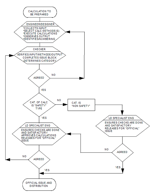
5. Flowchart
6. References
| Document | Title | |
| Number | ||
| 6.1 | SA-350 | Procedure to Assure Safety Design |
| 6.2 | QA-004 | Basic Design Data |
| 6.3 | QA-006 | Procedure, Approval and Control of Engineering Documents |
| 6.4 | CM-CA-001 | Development and Approval of Computer Programs |
| 6.5 | CM-PE-111 | Final Disposition of Project Documents |
| 6.6 | CM-MA-102 | Document Issue Code and Change Identification |
Figures: 
Authorization of Calculations
| Internal Issue | ||||
| Entry | Signatory | Responsability | ||
| A | Lead Engineer | Initial, dates confirm that document is internally issued ref. 6.6. | ||
| B | Add Company document number, see section 4.2.2. | |||
Internal Issue
| First Formal Issue | ||
| Entry | Signatory | Responsibility |
| 1A | Originator | Add formal issue number "I" |
| 1B | Add the revision description | |
| 1C | Initial to confirm that the calculations - Is without ambiguity - Have followed a consistent pattern - Have a neat presentation |
|
| 2A |
Lead Engineer Safety
|
Initial confirms |
| 2B | Signs only for a certified issue | |
| 3A |
Project Manager Nonsafety |
Initial to signify approval for
|
| 3B | Signs only for certified issue | |
| 4 | Project Clerk | Dates issue after checking and recording - Document numbering - Revision code Distribute document |
| Revised Issues | ||
| The revision of a calculation shall be handled as above, ref 6.6. Signatures and actions will follow the entries 1A/1B/1C/2A/3A/4. | ||
First Formal Issue
| Index of Calculations Calculation no. |
Title | Calc. Type See1) |
ISS | Date | Is authority Approval Req'd | Is Microfilm Film Required |
||||
| Yes/No | See 2) | Yes/No | See 2) | |||||||
| 1) Denote Safety/Integrity Type By: "Safety" Denote Other By: "Non-Safety" |
2) Indicate Approval Receipt By: "X" | 3)Indicate Microfilmed By: "X" | ||||||||
Index of Calculations
| INDEX OF CALCULATION SHEET ISSUES | |||||||
| SHEET NO. | ISSUE DATE | SHEET NO. | ISSUE DATE | SHEET NO. | ISSUE DATE | SHEET NO. | ISSUE DATE |
Index of Calculation Sheet Issues